Mold types
Seven types, each in its own section: which models it is for, what every setting in the sidebar means, the parts it generates and how the printed mold is used. The Fitted Box is described in the most detail; the silicone types share its settings and add only their differences. Slip Cast, a plaster mold, and Injection Mold, a rigid mold for plastic injection, have settings and sections of their own.
7.1 Fitted Box
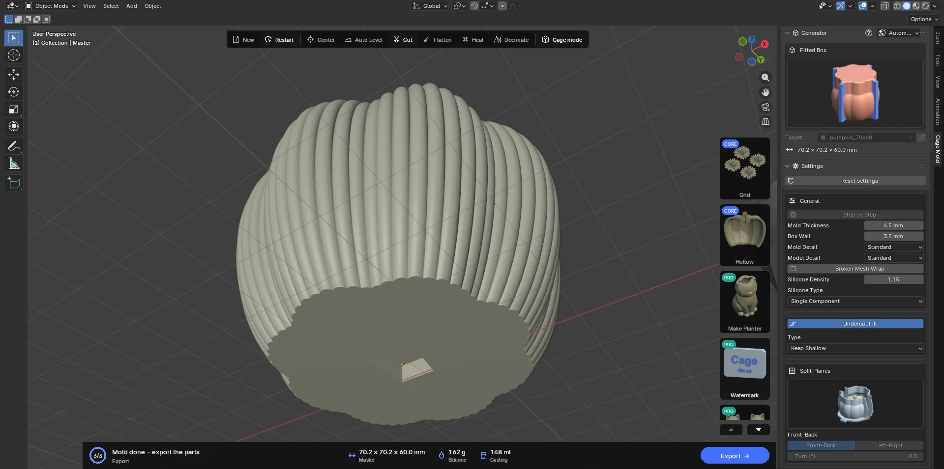
The general-purpose type. It wraps the model in at least Mold Thickness of silicone everywhere, splits the box at the split plane into two (or four) parts and designs each part so it pulls away from the silicone along its own direction. The box parts sit on the base plate's pins, their feet are pressed to the base by base clips, their seams held by seam clips. The silicone is poured through the funnel at the top.
Candles, vases, figures, decorative objects: for anything that comes out of one piece of silicone this is the first choice. For long candles closed all round Two-Part fits better, for complex shapes a one-piece skin cannot release Multi-Part, for hollow planters Cored Mold.
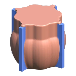
Two ways of working: Automatic and Step by Step
Automatic (the default): one button on the action card, Make Mold. The settings go straight to the finished mold. There is nothing to edit in between, so the draft step is skipped and it is faster.
Step by Step (the switch in General; CORE): two steps. Make Draft first builds a coarse draft: the silicone's shape, two channel plates (X and Y) and the funnel column (Funnel) come as separate, editable objects. Move, lengthen, shorten, thicken or delete the plates with Blender's tools; move the funnel and scale it in X/Y/Z. Nothing is recomputed while you edit; Confirm rebuilds the silicone at full detail from the objects you edited and generates the parts. Refresh Preview (at the top of the Settings panel) rebuilds the draft with new settings.
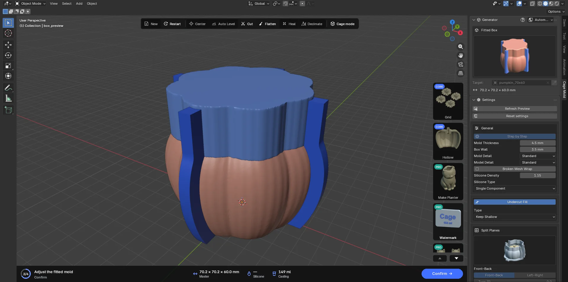
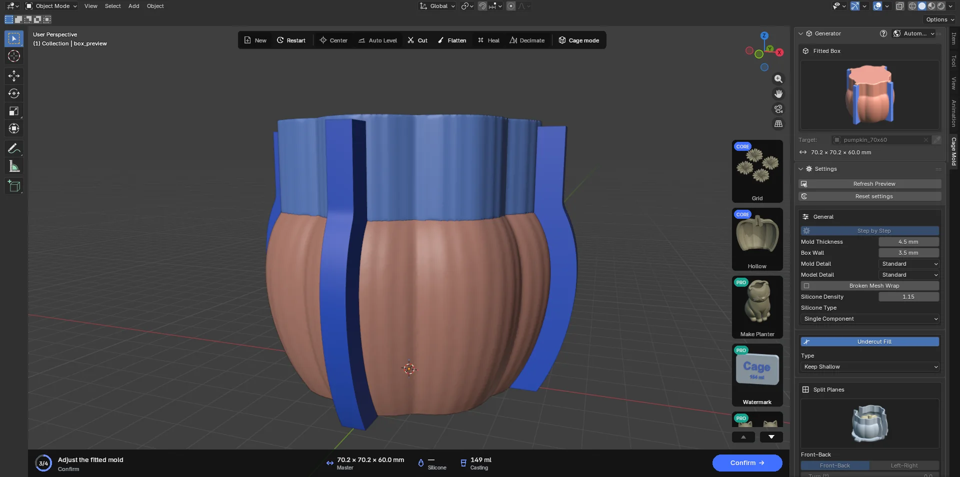
 General
| Setting | Default | Meaning |
|---|---|---|
| Step by Step | off | On: Make Draft › Confirm; off: Make Mold. Change it before the mold is built. |
| Mold Thickness | 4.5 mm | The least silicone around the model. Raise it (6 to 10 mm) for large, heavy casts (concrete) or finely detailed models. The silicone and the box grow with it. Two-Part, Multi-Part and Cored Mold have values of their own. |
| Box Wall | 3.5 mm | The wall of the printed box. 3 to 4 mm is sturdy on most printers. |
| Mold Detail | Standard | The resolution of the silicone and box surfaces: Quick (coarse, quickest), Standard, Fine, Finest (crispest, slowest; minutes on a large model). The draft is never finer than Standard; Confirm builds at the detail you chose. Fine and Finest are in the Core package; Lite builds at Standard. |
| Model Detail | Standard | How closely the printed model (welded to the base, or the keyed copy) follows the surface: Quick is the coarsest and quickest; Standard, Fine, Finer and Finest follow it ever more closely; Original uses the model exactly as it is. Even Standard keeps a face's detail. Fine and finer are in the Core package. |
| Broken Mesh Wrap | off | Turn it on when the box comes out unclean: the model's interior faces and self-intersections can then not reach the box. Takes longer. |
 Undercut Fill
Every box part has one extraction direction; the part slides off the silicone along it. The direction is chosen by itself to add the least silicone. Recesses that would block the pull (undercuts) are filled with silicone: the box does not go in there, the silicone does.
- Type · Keep Shallow (default; Type is a full-width list under the section's name): shallow undercuts up to 1 mm are kept; the cured silicone flexes over them. Less silicone, a slimmer box.
- Type · Fill All: every undercut is filled. For stiff silicones and very fragile casts.
- With the switch off no undercut is filled; that only makes sense when the model truly has none (a cone, a cylinder).
 Split Planes
- Front–Back: the plane that parts the box into a front and a back half. The default.
- Left–Right: the plane that parts it into a left and a right half. Both planes are upright; the box is never cut through its height.
- Both (Four Parts): four box parts. Easier extraction on models with many recesses. CORE
- Turn (°): turns the guides together about where they cross (−90 to 90). The whole box (plates, ears, base, casting box) turns with them; a turned split costs no more silicone. CORE
Click the guide in the view and move it with G to run the split where you want it, through the middle of a handle, say. The split changes only in the READY stage, and at least one plane is needed ("Enable at least one X or Y split"). The Lite package uses one plane; choosing both, or a Turn, brings a lock box in the section.
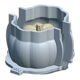 Front–Backdefault
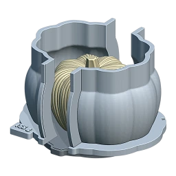 Left–Right
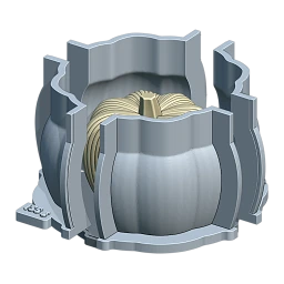 Four PartsCORE
 Channels
The channel plates are two flat plates inside the silicone, along X and along Y. Where the plate on the split plane reaches the silicone surface, the box gets two half seam ears; the seam clips grip these ears. A plate on a plane the box is not split on makes no ear: the box only wraps its fin, which shows from outside as a channel line.
- Adjusted (default): the plate draws a smooth curve parallel to the model's outline, and the box follows it. Less plastic and silicone, ears that hug the shape. The seam lock (Clamps) follows this band too.
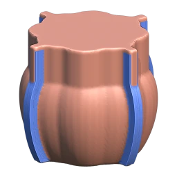
- Straight: the plates run flat to the model's widest extent; the box gets flat sides. Simple and sturdy. Scenes saved with older versions open as Straight.
- Width (6 mm): the plate's thickness; the ear's total thickness is Clamps' Width.
- Depth (6 mm): how far the plate reaches past the silicone surface.
With the switch off there are no plates and no ears; only the base clips and, if any, the Casting Box hold the seams.
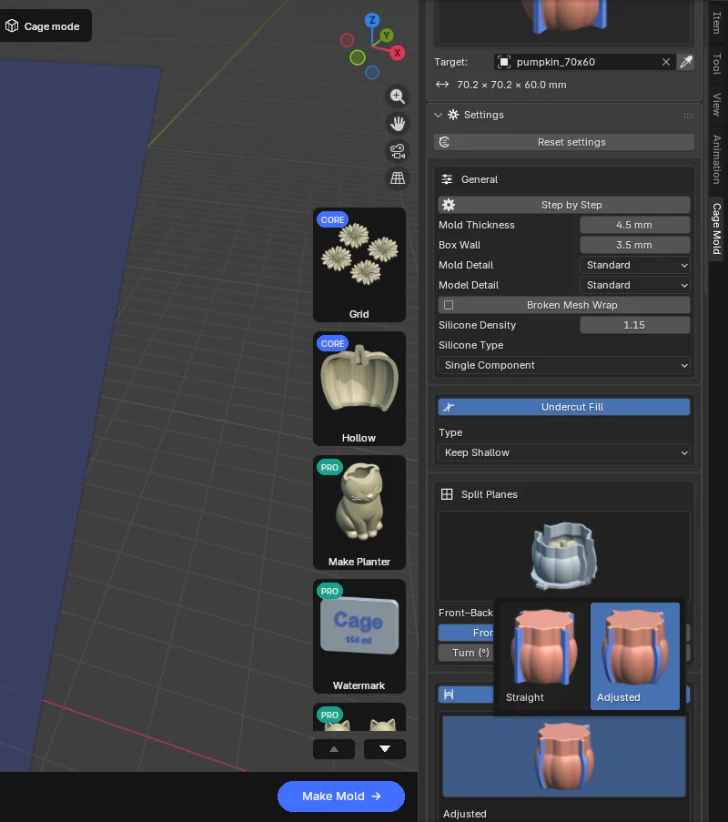
 Adjusteddefault
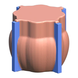 Straight
 Base
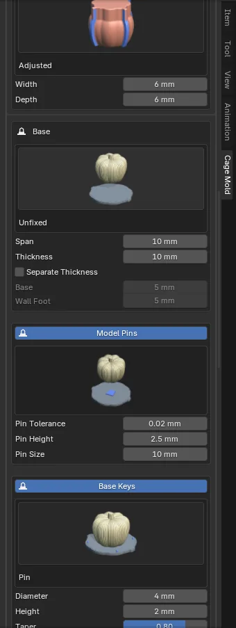
Master: how the model is joined to the base.
- Fixed (default): the model copy is welded into the base plate and the two print as one piece. The simplest and sturdiest way.
- Unfixed: the model stays loose; Model Pins stand on the base and matching sockets are cut into the model's underside (the Model Pins section's title bar is its switch, on by default). You print the model separately (perhaps in another material, on another printer) and drop it onto the base. The keyed model copy is written by Export. Seen from above a key is a trapezoid (one side narrower) and it tapers slightly upwards: the model goes onto the base only the right way round and seats without wedging. One key stands under each foot of the model (at most four).
- Pin Tolerance (0.02 mm): the clearance between socket and pin.
- Pin Height (2.5 mm): how far a pin stands above the base.
- Pin Size (10 mm): the key's width across its wide side, and its length. A key that does not fit under the model's foot is made smaller by itself and Confirm says so ("Model Pins: 10 mm does not fit under the master; made 7.5 mm").
Dimensions
- Span (10 mm): how far the wall foot and the base plate reach beyond the box wall.
- Thickness (10 mm): the total of the foot and the base plate; each gets half.
- Separate Thickness: gives the foot (Wall Foot, 5 mm) and the plate (Base, 5 mm) thicknesses of their own.
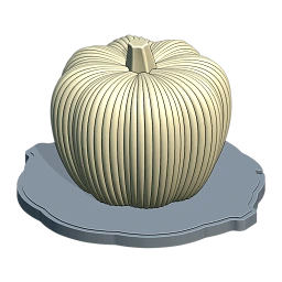 Fixeddefault
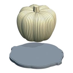 Unfixed
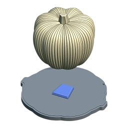 Model Pins
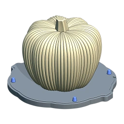
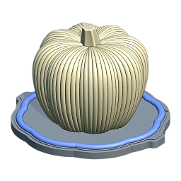
Base Keys (its title bar is the switch): how the box parts' feet register on the base.
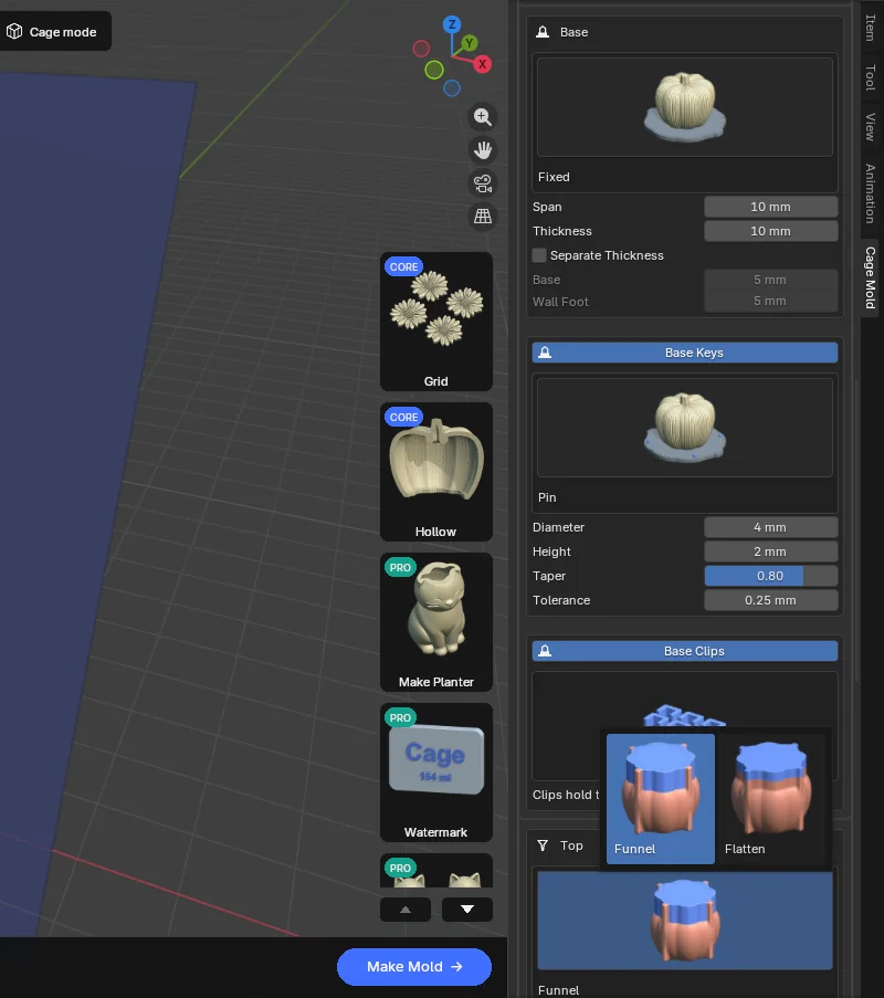
- Pin (default): two tapered pins per part rise from the base into holes in the feet. Diameter 4 mm, Height 2 mm, Taper 0.8 (the top diameter as a share of the bottom), Tolerance 0.25 mm.
- Barrier: one rounded rib all the way around the foot ring (male on the base, a groove in the foot, widened by Tolerance). Aligns better along long edges.
Base Clips (on by default): six U clips in two rows of three, whatever the number of parts; they press the feet to the base and stop the box from lifting while you pour. The clips come as the object base_clips, laid side by side.
 Pindefault
 Barrier
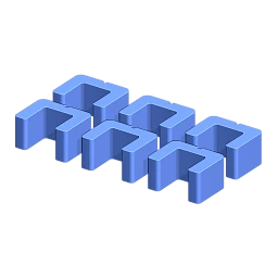 Base Clips
 Top
- Funnel (default): from Funnel Height (80 % of the model's height) the box walls go straight up and end Mold Thickness + Extension (5 mm) above the model's crown. The silicone is poured to that rim: the model's crown is covered by Mold Thickness + Extension of silicone. Funnel Scale (1.00) scales the X/Y footprint of the funnel column (in Make Mold too; in Step by Step scaling the Funnel object changes it as well).
- Flatten: a flat, open top instead of the funnel. The upper Height mm (10 mm), up to the rim (model top + Mold Thickness), become a straight column of that section. Flatten Entire Top straightens the whole height: the column takes the silicone's outline seen from above, from the floor to the rim, nothing sticks out of it, and Height greys while it is on. The Flatten… button asks the same settings, and Bottom for the lower side, in a dialog; Flatten in the strip is a small popover with Height and Flatten Entire Top (Flatten Top). In the draft stage both apply to the draft at once.
Flatten Bottom (under both tops, at the end of the section): makes the silicone's lower part a straight column too, its own Height (10 mm) high; its checkbox here, or Bottom in the Flatten… dialog, turns it on.
The box rim stands Mold Thickness + Extension above the model's crown with a Funnel, Mold Thickness with Flatten; the silicone is poured to the rim. The casting box reaches exactly that height too.
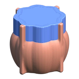 Funneldefault
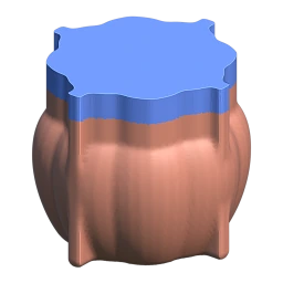 Flatten
 Clamps
 · Barrier / Pin / None (the seam lock): a lock moulded into the seam faces so the halves close only one way.
- None (default): a bare seam.
- Barrier: a rounded rib along the seam band; male on one half, a socket Tolerance larger on the other. With Adjusted channels it follows the band's curve.
- Pin: a column of spheres on the same line.
- Note: the Barrier and Pin locks are sized to the ear: the default 6 mm Width gets a 3 mm key, and a thicker ear a bigger one. Below a Width of 5.75 mm no lock is made and Confirm says so ("Clamp Barrier lock skipped: the flange is too thin…").
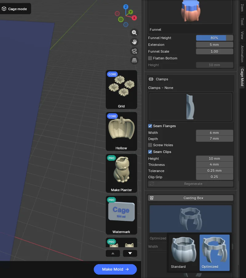
Seam Flanges (the seam ears, on): Width (6 mm) is the ear's total thickness (each half gets half), Depth (7 mm) how far it stands past the wall. Screw Holes (off by default) cuts Screw Diameter (4 mm) holes through both ears; a bolt closes the seam where a clip would be in the way.
Seam Clips (on; greyed while Seam Flanges is off): the eight U parts that press the ears together. Height (10 mm; a clip prints lying flat, this is its thickness on the bed), Thickness (4 mm; the back and arms), Tolerance (0.25 mm; clearance added to the two ears), Clip Grip (0.25 mm; how much narrower the mouth is than the ears, so the arms lean in and grip). Regenerate rebuilds only the two clip groups (seam and base) with new values, without rebuilding the mold; it sizes them for the ears and base the mold was built with. It works with Seam Flanges off too (it makes the base clips as well).
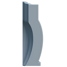 Nonedefault
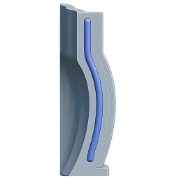 Barrier
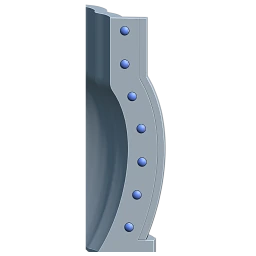 Pin
 Silicone
The silicone you pour and its recipe. The list at the top of the section picks a ready recipe, which fills the rows under it:
- RTV-2 · Shore 5, 10, 15, 20, 25, 30 (RTV-2 · Shore 10 by default): silicone mixed with a catalyst. It sets Silicone Type to Single Component, Catalyst to 2 % and the demold time to 8 hours. The Shore number is the silicone's hardness; a lower number makes a softer, more flexible mold, a higher one a firmer mold.
- Platinum (A/B) 1:1: silicone whose parts A and B are mixed one to one by weight. It sets Silicone Type to A/B and Mix A : B to 1 : 1.
- Custom: you enter the values yourself; this choice also brings a Shore A row. Changing Silicone Type, Mix, Catalyst or Shore A by hand turns the list to Custom.
| Setting | Default | Meaning |
|---|---|---|
| Silicone Density | 1.15 | The silicone's density (g/cm³). The silicone's grams are worked out with it; enter the value from your silicone's data sheet. A recipe leaves it alone, and changing it does not turn the recipe to Custom. |
| Silicone Type | Single Component | Single Component: a silicone and its catalyst (RTV-2). A/B: a two-part silicone; Mix A : B is the mix by weight (1 : 1, 10 : 1…). |
| Catalyst (%) | 2 | Single Component only: the catalyst as a share of the silicone's weight. At 0 one weight is given. |
| Mix A : B | 1 : 1 | A/B only: the maker's ratio by weight. |
| Shore A | 10 | Custom only: the silicone's hardness. The mold sheet writes it as "Custom · Shore 15". |
| Expected Casts | 30 | How many casts you expect from the mold. The mold sheet's silicone cost per cast is divided by it (chapter 8). |
Every type that pours silicone has the Silicone section (Tray, Cored Mold, Two-Part, Multi-Part); Slip Cast and Injection Mold do not.
 Casting Box PRO
A second, thin shell that wraps the cured silicone mold while you cast, split where the mold splits and carrying the same ears (the same seam clips fit). Out of its box the silicone mold is soft, so on large, thin-walled molds the cast would deform; the casting box prevents that. Off by default; click the section's title bar to turn it on.
- Standard: the whole shell.
- Optimized (default): only bands Width (15 mm) wide along the split planes plus one Ring at the top or the bottom. Both axes get a band even when the box splits on one, so the cage closes on all four sides. Less plastic, a quicker print.
- Separate Thickness: gives the casting box its own Wall Thickness (5 mm).
The casting box reaches from the floor to the top of the silicone and never above it. Its parts come named like casting_part_01 and are exported. Ring is Top by default.
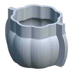 Standard
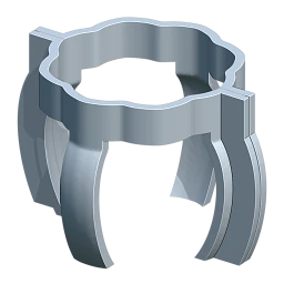 Optimizeddefault
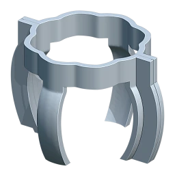 Ring · Top
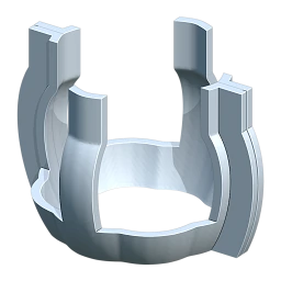 Ring · Bottom
The parts generated
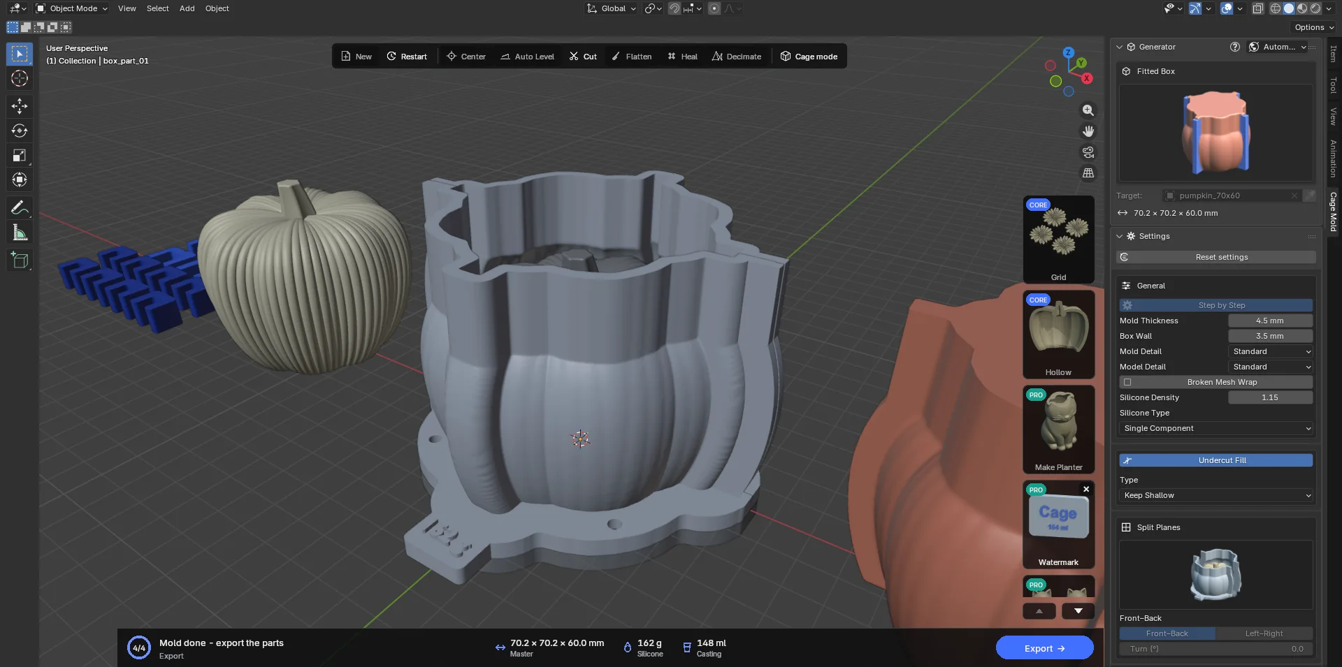
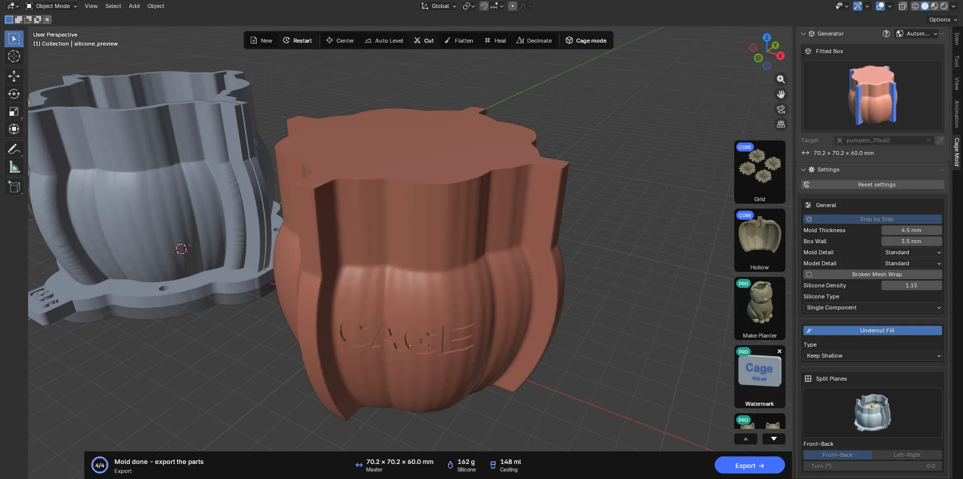
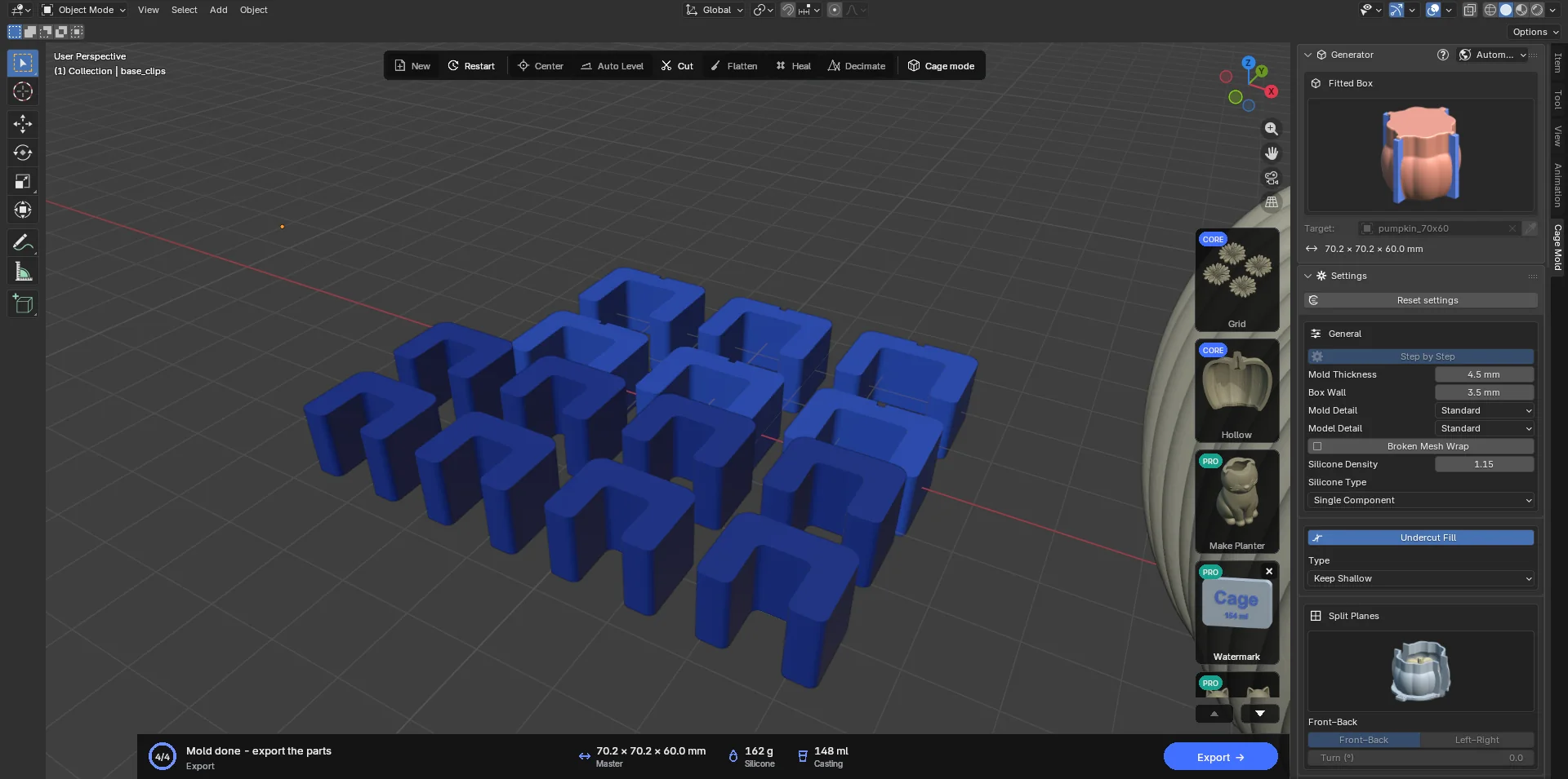
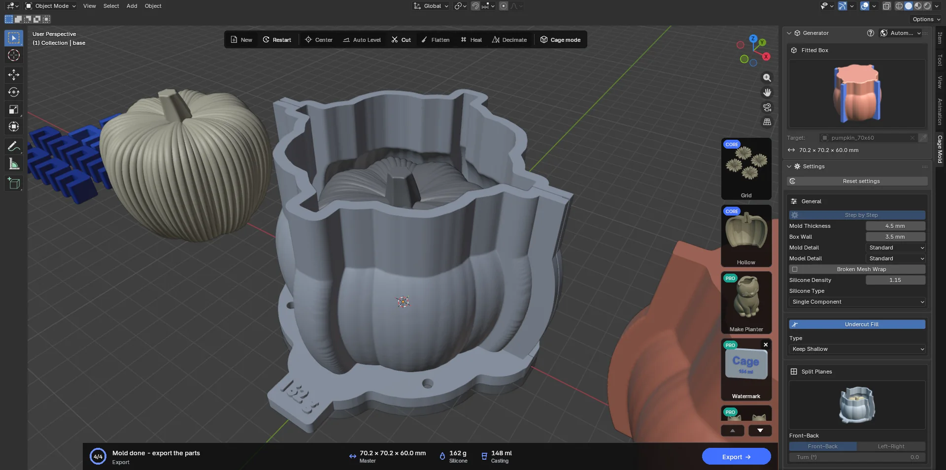
| Object | Printed | What |
|---|---|---|
| box_part_01, 02 (…04) | Yes | The box parts: wall, foot, seam ears, base pin holes, the weight label tab (on part 01's foot, "155 g"; with A/B silicone "A 78 g B 77 g"; none on Lite). |
| base | Yes | The base plate with the welded model copy, the pins or barrier, the orientation notch. |
| base_clips | Yes | The base clips, six of them. |
| seam_clips | Yes | The seam clips, eight of them (with Seam Flanges and Seam Clips on). |
| casting_part_… | Yes | The casting box parts (with Casting Box on). |
| silicone_preview | No | The silicone preview; the volume and weight are read from it. |
| Master | No (Unfixed + Model Pins: yes) | The model copy; with Unfixed and Model Pins, the keyed copy to print. |
Using the printed mold
- Assemble
Put the base on a flat surface. Seat the box parts by the holes in their feet on the base's pins; the orientation notch (the 3 × 3 mm slot through foot and base) shows the right way round. Push the seam clips onto the seam ears and the base clips onto the feet. You can tape the seams and the feet or seal them with a little clay so no silicone leaks.
- Pour
Prepare silicone to the Silicone weight on the action card (add 5 % for losses), mix it well, degas it if you can and pour it slowly through the funnel in a thin stream onto one spot. Fill to the rim.
- Take apart
Once the silicone has cured, take off all the clips. Over the ears' outer 2 mm a gap of about 0.6 mm is left between the halves; pry them apart there. Pull every part along its own direction (normal to the seam, slightly tilted). Lift the silicone off the base and take the model out.
- Cast
The silicone mold is used on its own or inside the casting box: put the mold in the casting box, push on the seam clips and pour the casting material through the model's footprint (the mold's open face). The Casting volume is the amount you need.
7.2 Tray
A pan with a flat floor, printed as one piece. The model is fixed to the pan's floor; silicone is poured over it and, once cured, the block lifts straight up out of the pan. The block's flat face that sat on the floor is the mold's open face. Ideal for flat models, reliefs, embossed plates, soap and candle molds and small parts multiplied with Grid. In every package.
A tray has no seams, seam clips, separate base plate or base keys (with Unfixed, the model's pins stand in the pan's floor); since no box has to come off the silicone, undercuts are "swept" upwards instead: every section contains the one below it, so the block lifts out without catching and no air is trapped while pouring. A model with a hole through its middle (a frame, a ring, a daisy with a window) molds safely too: the poured silicone does not run out through the hole, it stays in the pan.
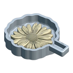
Settings
The Tray's sidebar is short: everything the type does not use is hidden (Undercut Fill, Split Planes, Channels, Top, Clamps, Broken Mesh Wrap).
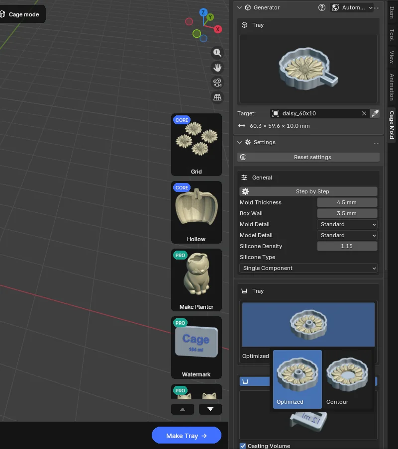
Tray · Type
- Optimized (default): the pan follows the model directly; the model's holes stay open in the mold: the pan leaves an island inside the window, and the silicone has a hole there.
- Contour: the pan follows the model's outline and covers its holes and the faces left inside it. An open-backed relief also keeps the whole Mold Thickness of silicone round its edge. Use it on rough scans and models with a muddled inside.
Grip (on; its title bar is the switch): a handle to pull the silicone block out by. A pocket opens on one side of the pan; the poured silicone fills it too and the cured block comes out with a handle. The pocket is walled all round and the handle's top is flush with the pan's rim. The silicone's weight ("178 g"; both shares with A/B silicone) is engraved on the pocket's wall CORE. Casting Volume CORE (on) cuts the casting volume ("32 ml") mirrored into the pocket's floor, so it reads the right way on the silicone. With Grip off the weight goes on top of the pan's +X rim; the casting volume can be written only in the handle, so then it is left out.
General: Step by Step, Mold Thickness, Box Wall (the pan's wall and floor), Mold / Model Detail, as in the Fitted Box. The Silicone section is the Fitted Box's too (7.1 Silicone).
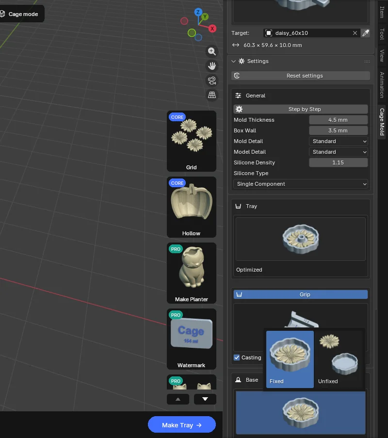
Base: only Master Fixed / Unfixed (and Model Pins with Unfixed). With Fixed the model is welded into the pan's floor and printed with it; with Unfixed the model prints on its own and sits on pins in the pan's floor; the pins' Pin Tolerance (0.02 mm), Pin Height (2.5 mm) and Pin Size (10 mm) work as in the Fitted Box (7.1 Base).
Casting Box PRO: a floorless copy of the pan's walls and grip pocket (casting_tray), cut 1 mm above the model's base. The cured block goes back into it, turned over, and is cast in there. Standard is the whole frame, Optimized bands Width wide (5 mm on a tray) through the middle of each side, with a Ring (Top or Bottom; Top by default). Separate Thickness gives the casting box its own Wall Thickness (5 mm).
The strip's Flatten is off for a tray: its top is flat and open already.
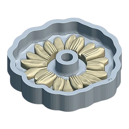 Optimizeddefault
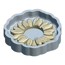 Contour
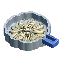 Grip
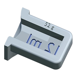 Casting VolumeCORE
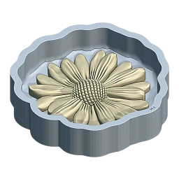 Fixeddefault
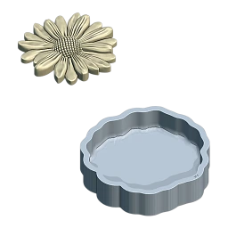 Unfixed
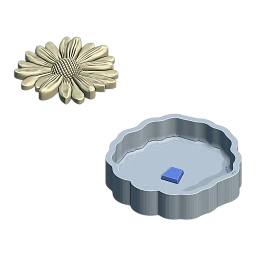 Model Pins
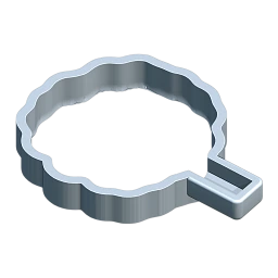 Casting Box · StandardPRO
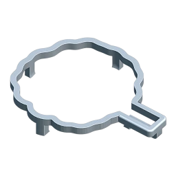 Casting Box · OptimizedPRO
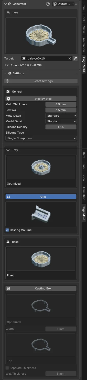
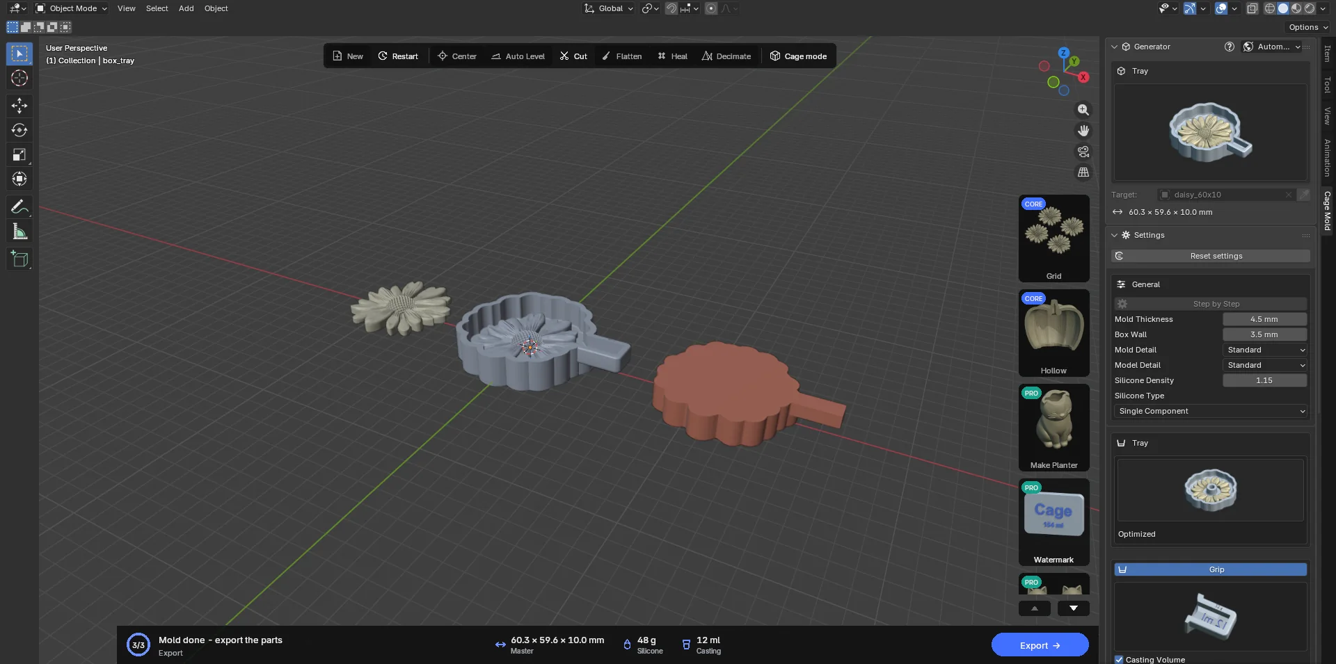
Workflow and result
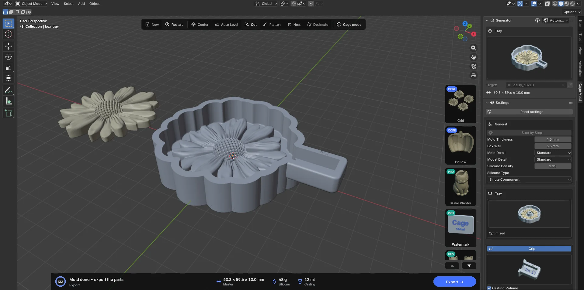
In Automatic one button, Make Tray. In Step by Step Draft Tray builds the pan and an editable grip object: move it to any side with Blender's tools, turn it, scale it or delete it (deleted, that mold has no grip). Confirm puts the grip on the side it stands out on most, its top flush with the rim; the labels turn with it. Even when Mold Thickness changes after Draft Tray, the grip's top stays at the rim.
The objects that come out: box_tray (printed), silicone_preview (the preview) and Master (the model copy); with Casting Box on, casting_tray is printed too.
Use: print the pan, prepare silicone to the weight on the action card and pour it to the rim (the grip pocket fills too). Once cured, hold the handle and pull the block straight up. To cast, put the block open face up on the table or into the casting tray and pour; the volume written on the handle is all the material you need.
7.3 Cored Mold PRO
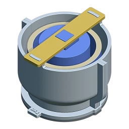
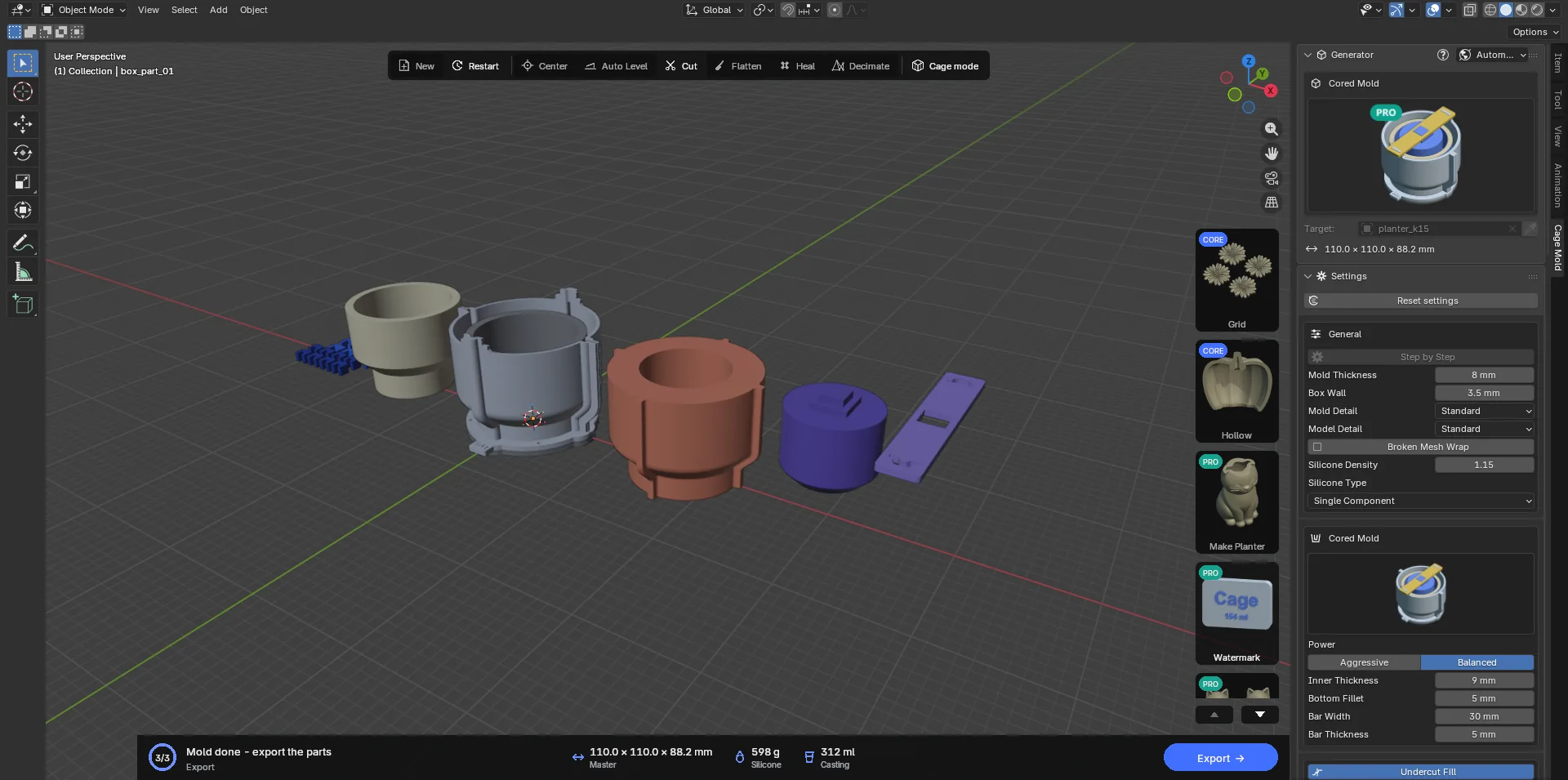
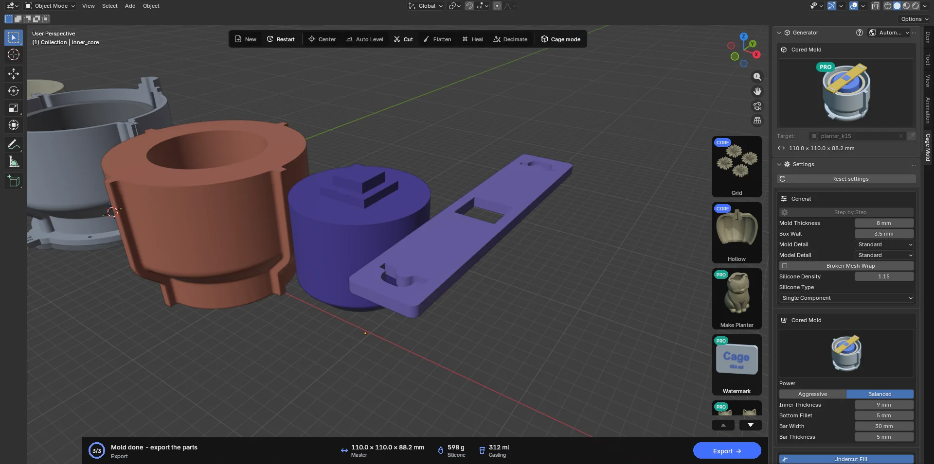
A Fitted Box for hollow models (planters, candle holders, bowls): a printed core goes into the model's hollow, so instead of a silicone plug only a skin Inner Thickness thick remains there. It saves a great deal of silicone. The core is held by a printed bar across the box's rim: the bar's slots sit on two tabs on the box wall and the core's square key comes up through the hole in the bar's middle. After curing the core lifts straight up and out. The core never goes below the model's bottom, so it does not come out through a drainage hole or a bottomless sleeve. When the top's centre has no room (a ring-shaped top, say), the key goes on the top's widest point.
Everything else is the Fitted Box's: Automatic / Step by Step, splits, channels, base, clamps, casting box. The Top section shows one line instead of a picture card: "Poured flat to the rim: no funnel". This type has its own Mold Thickness, in General, 8 mm by default; a file saved before 1.0.1 keeps its old values. Turn in Split Planes turns the split guides, and the bar turns with them, lying diagonally for example. The core and the bar are made at Confirm: the draft does not show them (the hollow shows full of silicone in the draft; that is no error), and the status bar says Confirm builds the core and its bar at full detail.

| Setting | Default | Meaning |
|---|---|---|
| Mold Thickness | 8 mm | This type's own value (in General): the silicone round the model's outside. |
| Power | Balanced | Which hollows get a core. Balanced: a hollow gets a core, its key made smaller to fit down to a 12 mm tab; a smaller hollow stays silicone. Aggressive: smaller hollows get a core too, the tab down to 6 mm. |
| Inner Thickness | 9 mm | The silicone between the hollow's walls and the core. It follows this type's Mold Thickness, 1 mm thicker, until you set it by hand (outside and inside are two settings). |
| Bottom Fillet | 5 mm | The radius that rounds the core's bottom edge (0 = sharp). |
| Bar Width | 30 mm | The width of the bar, of the core's step and of the pedestals the bar rests on. At least 26 mm; a narrower bar is not strong enough. |
| Bar Thickness | 5 mm | The bar's thickness. The core's and the box's tabs stand above the bar at any thickness. |
Result: besides the Fitted Box's parts, inner_core (the core; solid, the slicer's infill lightens it) and core_bar (the bar); both are exported. The note on the action card tells you about a key made smaller, a hollow left without a core, or no core at all.
Use: assemble the box, bring the core over the hollow with its key up, seat the bar on the box's tabs with the key through its hole; the core hangs in the hollow. Pour the silicone to the rim. Once cured, take the bar off, pull the core up and take the box apart.
7.4 Two-Part Mold CORE
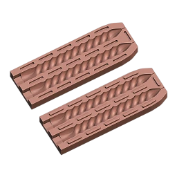
Two silicone halves that close on a plane through the model's axis. For models closed all round, above all long thin candles (twisted, tapered); several candles are cast side by side in one mold. Each half is poured in its own box, parting face down; the cured halves close on their keys (Barrier bars or Pin studs) and are held in a printed casting cage. The wax is poured through the square pour head at the open base end; the wick runs through the wick channel out of every cavity's tip.

| Setting | Default | Meaning |
|---|---|---|
| Cavities | 2 | How many copies of the model are cast in one row (1 to 8); a row of keys fits between them. |
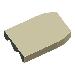
| Back | Flat | Flat: each half has a flat back; the silicone is poured to the box's rim. Contoured: the back follows every cavity at Mold Thickness, the keys stand on a flat flange; the half is cast under a printed lid that then holds it while you cast. About a third less silicone. |
| Key Type | Barrier | Barrier: long round-ended bars along the cavities. Pin: dense rows of round studs. Male keys on half A, sockets in half B. |
| Key Size | 5 mm | A stud's diameter or a bar's width. |
| Key Tolerance | 0.5 mm | The sockets are this much larger on each axis; a closed pair has half of it all round. |
| Open Bottom | on | The cavity opens through the mold at the model's base, where the wax is poured. Off, the base is covered with silicone too. |
| Reservoir | 15 mm | A square pour head beyond the base, as wide as the base, cut off the candle after casting (0 = none). |
| Wick Channel | on, 1.5 mm | A round channel from every cavity's tip out of the mold, and its diameter. |
| Mold Thickness | 8 mm | This type's own value: the silicone over the cavities, at the backs and past the tips. |
 Back · Flatdefault
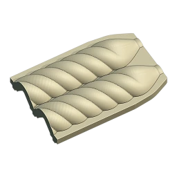 Back · Contoured
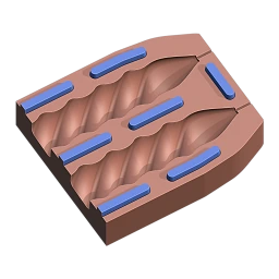 Key · Barrierdefault
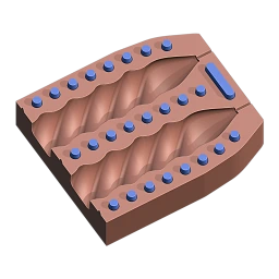 Key · Pin
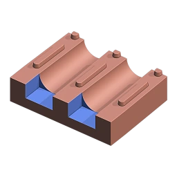 Open Bottom
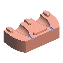 Wick Channel
The other sections: General (Step by Step, Box Wall, Detail), Base (Span, Thickness, Separate Thickness, Base Keys and Base Clips; a half is always printed with its base), Clamps, Silicone and Casting Box are the Fitted Box's; the Casting Box's cage is in the Pro package PRO. Split Planes, Undercut Fill, Channels, Top and Broken Mesh Wrap do not exist for this type: the halves are flat-backed slabs, and their boxes come off as two wall parts split across the middle.
The Casting Box becomes a cage. With Casting Box on (Back Flat) a casting cage holds the closed mold while you cast: a tray per half (A_cage, B_cage) and clamps that squeeze them (cage_clamp_NN). The trays hold the mold upright, pour end up; tray A carries a wick bar with a hole on every cavity's axis that keeps the wick centred. The clamp options: Ring (default; closed bands slid on from the cage's narrow end, which cannot spring open and press the middle of the backs too) or Claw (U parts pushed on from both sides). With Back Contoured there is no cage: the lids hold the halves, and the two lids' flat backs are banded together.
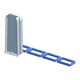 Clamps · Ringdefault
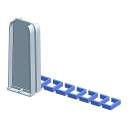 Clamps · Claw
Result and use
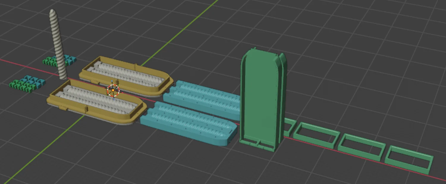
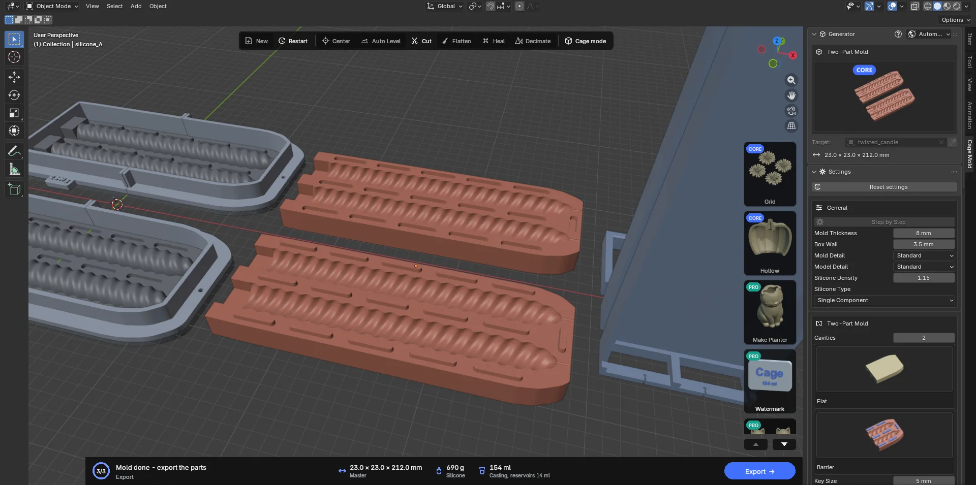
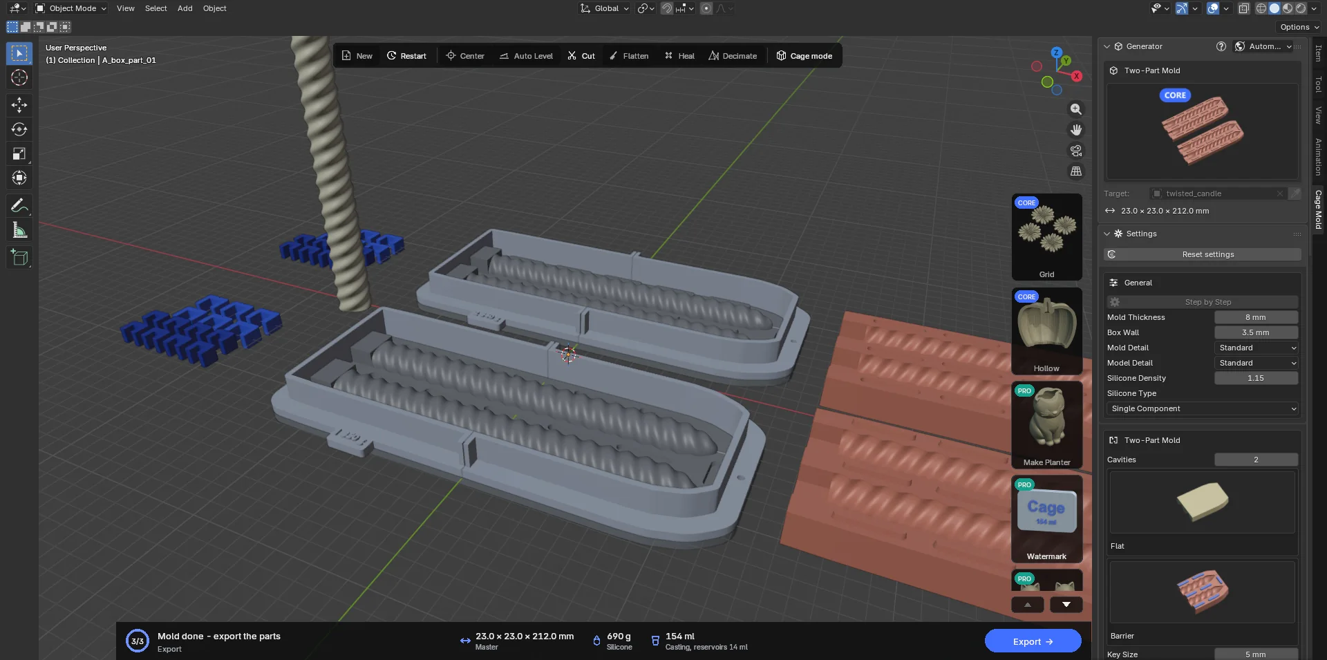
- Pour the halves
The object names start with
A_andB_; each half's base plate is the parting face, printed as one piece with the half-cavities, the pour head, the wick channel and the keys. Assemble both boxes and pour the silicone to the rim. The action card gives the silicone's total weight (with A/B silicone each part's share); each box's label carries its half's number and weight ("1 353 g", "2 340 g"). - Close
Take the cured halves out of their boxes and close them, A's bars into B's sockets. Thread the wick through the channel at the tips.
- Cage and cast
Put the closed mold between the two trays, slide the rings on from the narrow end (the pour-end ring first) or push the claws on from both sides. The cage stands pour end up on the extensions of the backs; the wick bar keeps the wick centred. Pour the wax through the pour head and cut the head off once cool.
7.5 Multi-Part PRO
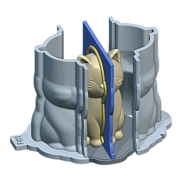
Two or four keyed silicone parts from one pour. For models a one-piece skin cannot peel off (a sitting animal, a bust, figures with arms) and any casting material (wax, concrete, resin). Printed split walls (dark blue) divide the silicone into parts while it is poured; the round keys on the walls make the sockets and studs the parts lock into each other with. The box holds the silicone parts together for the pour and for every cast afterwards.
The model is printed as one model plate together with the base plate and the split walls. The mold runs on the Fitted Box's pipeline; in Step by Step the draft (plates, funnel) is edited the same way.

| Setting | Default | Meaning |
|---|---|---|
| Split Planes | Front–Back | Where the mold splits, with this type's own pictures: Front–Back, Left–Right, both = four parts. Recenter Planes puts the guides back through the model's centre. The guides are not turned from the sidebar; turn the model instead. If a guide is dragged off the model, Make Draft and Make Mold stop and say so. |
| Bottom | Open | Open: the silicone ends at the model's bottom and the mold opens there; the model is welded to the base. Closed: the silicone runs under the model too, the model hangs on the split walls, and the cast is poured through a Pour Channel (8 mm) at the top. |
| Model Plate | Single Plate | Single Plate: the base plate, the model copy and the split walls in one printed piece. Part by Part: one model plate piece per silicone part; each carries its own half of the wall with its keys, pinned to the next across the plate's cut. |
| Split Wall | 3 mm | The printed wall between two silicone parts. The model and the mold are spread by it; the closed parts leave the model's exact shape. |
| Seam Keys | Barrier | Barrier: a round tube along every seam; Pin: a row of spheres. |
| Key Diameter | 4 mm | The key's diameter; half of it stands proud of the wall. It is limited so that enough material stays behind it in the split wall; a larger value is made smaller and Confirm says so. |
| Key Tolerance | 0.25 mm | The male keys are this much smaller than their sockets. |
| Mold Thickness | 4.5 mm | This type's own value: the silicone skin around the model. |
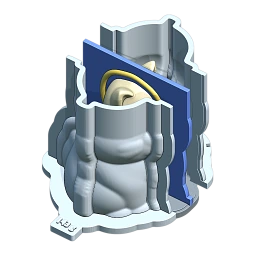 Split Planes · Front–Backdefault
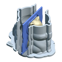 Split Planes · Left–Right
 Split Planes · both
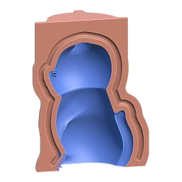 Bottom · Opendefault
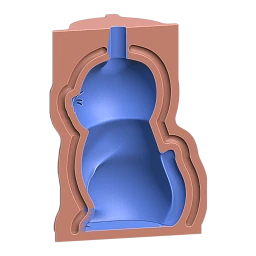 Bottom · Closed
 Model Plate · Single Platedefault
 Model Plate · Part by Part
 Seam Keys · Barrierdefault
 Seam Keys · Pin
The other sections: General (Box Wall, Detail, Broken Mesh Wrap), Undercut Fill, Top (Funnel / Flatten), Base (Span, Thickness, Separate Thickness, Base Keys — Barrier by default — and Base Clips), Channels (one plate on X and one on Y; the plate on a split plane is the seam fin that carries the keys), Clamps, Silicone and Casting Box are the Fitted Box's. The seam clips come in two sets, as the line in the Clamps section says: pour clips (holding two ears and the wall between them while the silicone is poured) and cast clips (holding two ears alone while you cast). With Channels off, the keys run the whole length of the seam. The model is always part of the model plate (there is no Fixed/Unfixed choice).
In Step by Step. Change Channels' Width, Depth or Type, or Mold Thickness, after Make Draft and the action card says "Settings changed: Refresh Preview redraws the draft; Confirm builds with them": Refresh Preview redraws the draft, and Confirm builds with the new values either way. The draft takes no watermark ("Confirm first: the watermark goes on the printed parts"); Confirm first, then put the watermark on the printed parts. A mark on the model plate keeps the wall's and the keys' colours.
Result and use
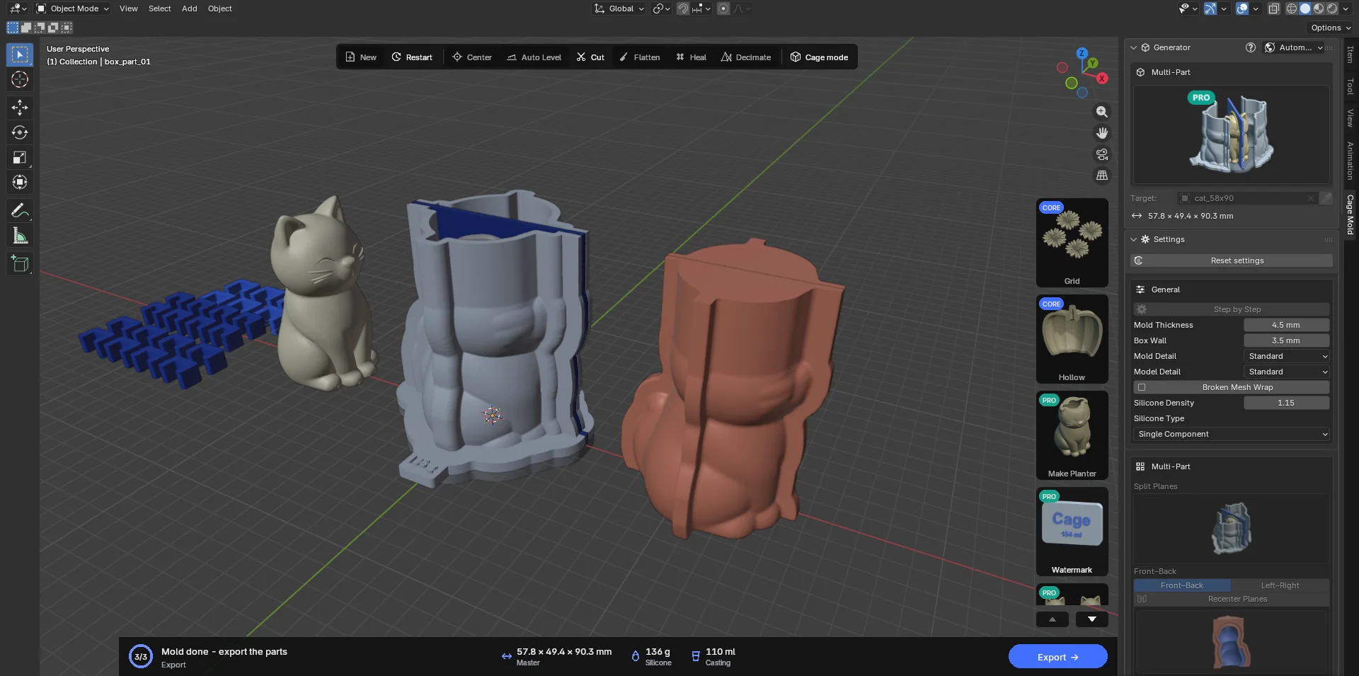
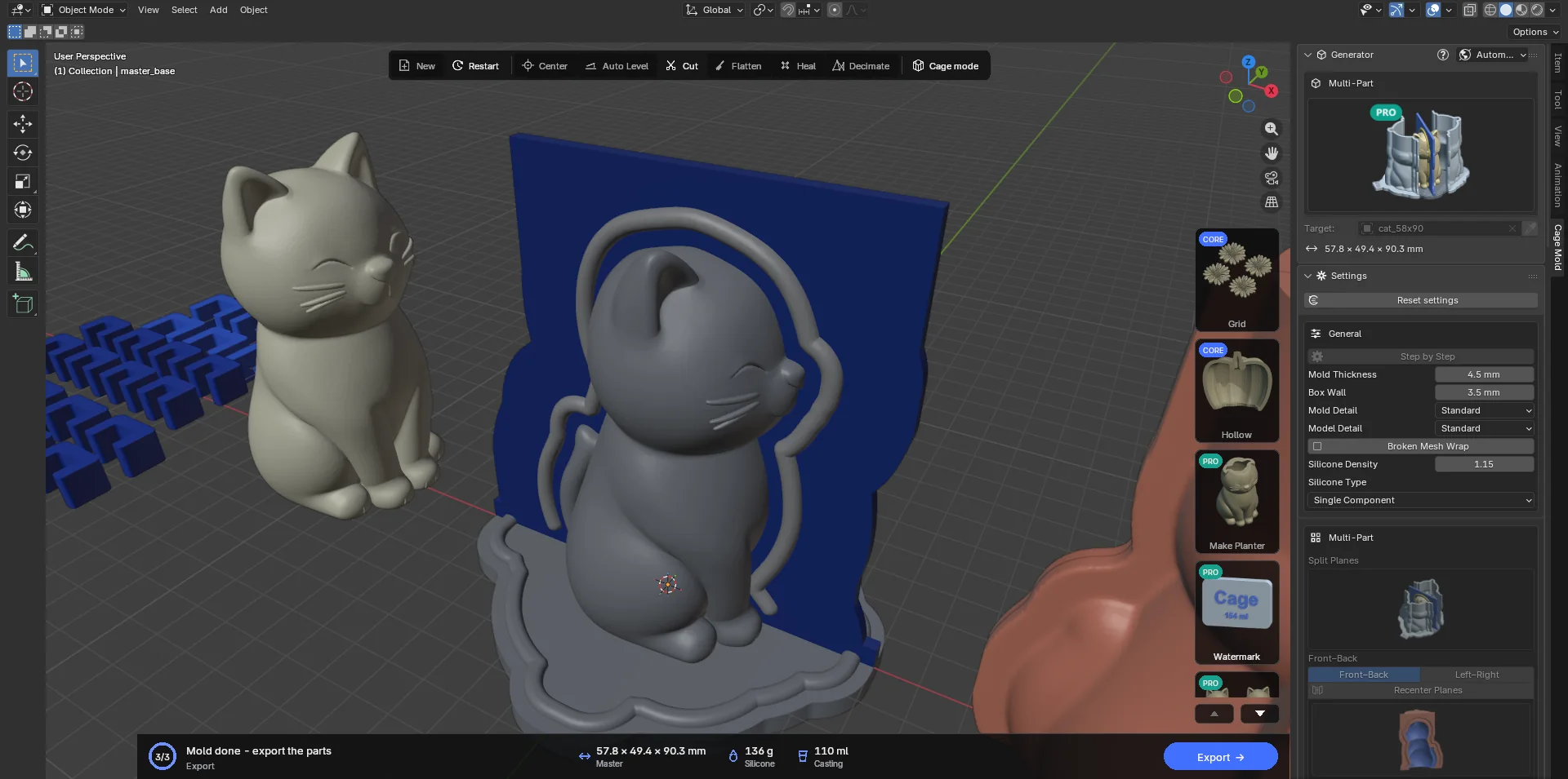
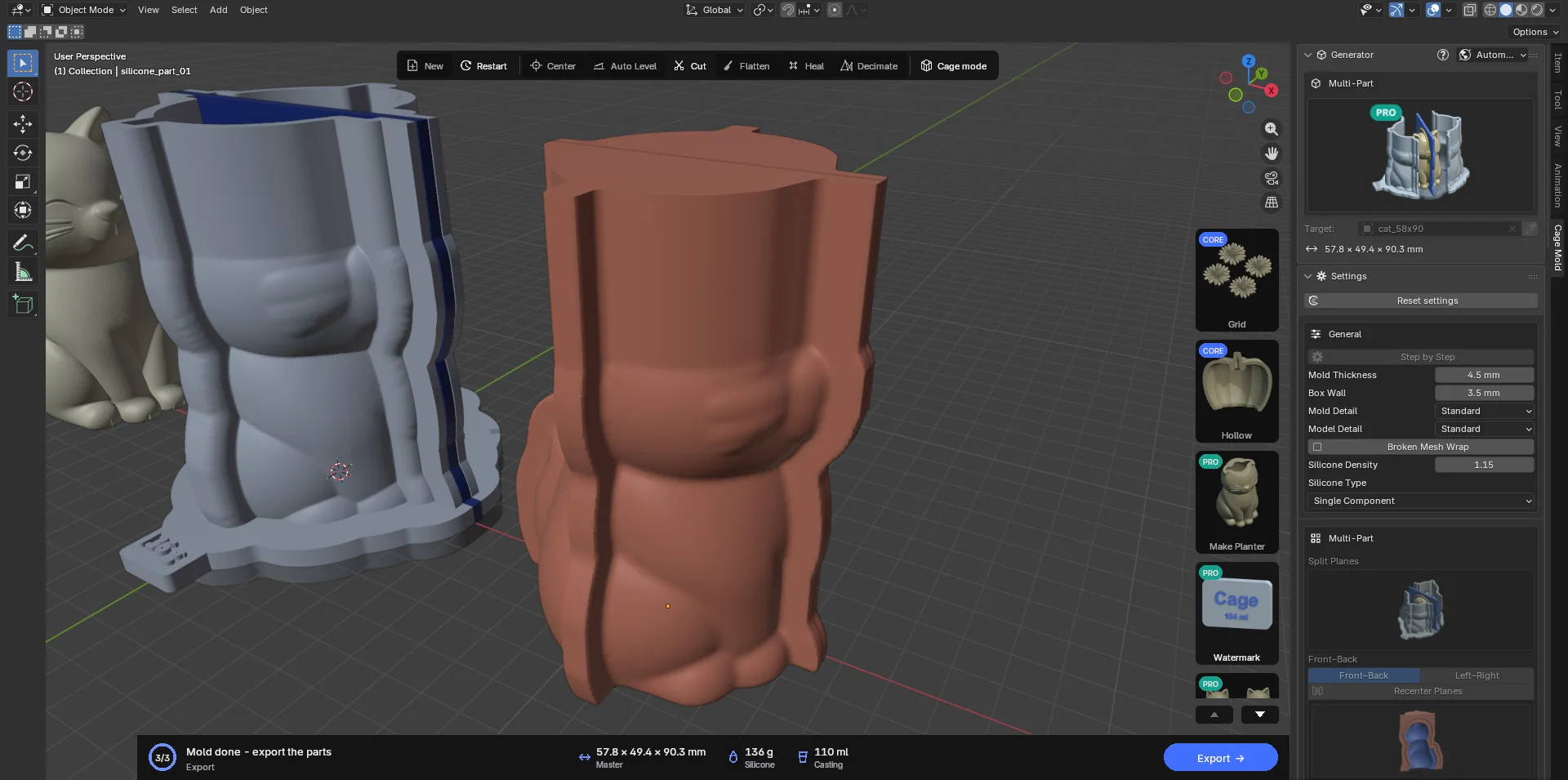
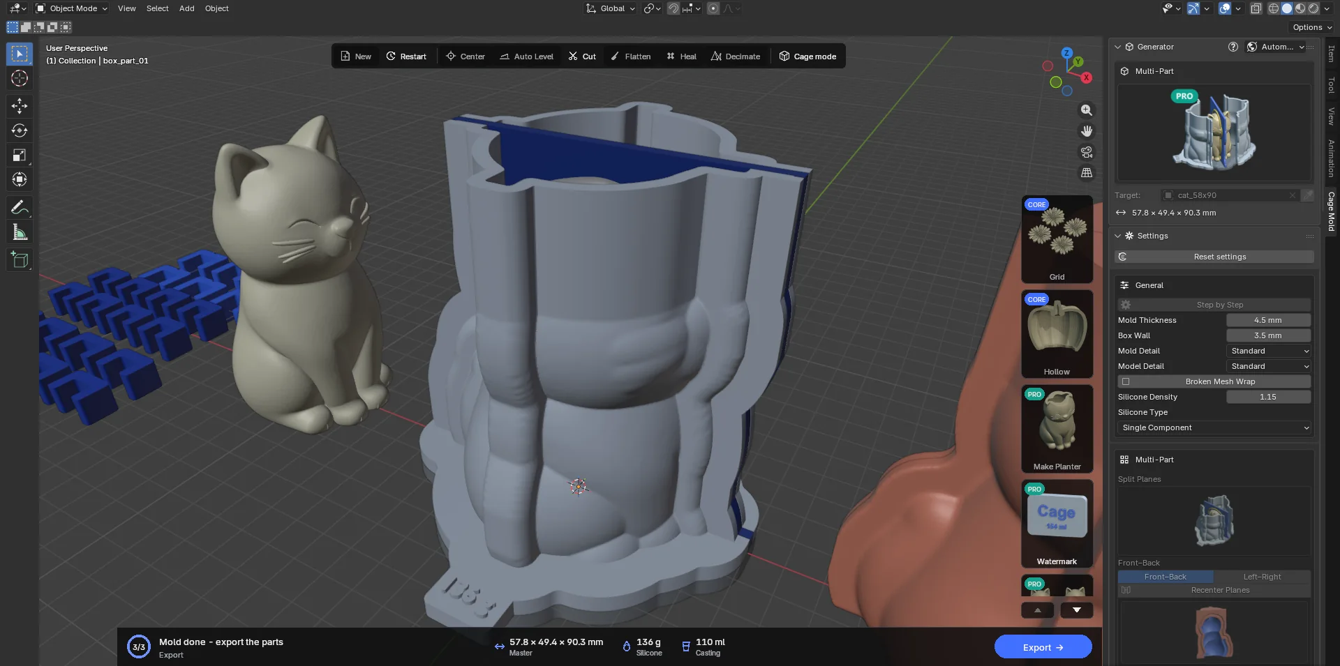
- Pour
Put the model plate (plate + model + walls) on the table, seat the box parts on the base keys (Barrier by default), push the pour clips onto the ears (with the wall between). Pour the silicone through the funnel (with a Funnel top; with Flatten, over the top); the walls divide the funnel too, so every part takes its share in the same pour.
- Take apart
Once cured, take off the clips and the box parts, and peel the silicone parts off the walls and the model. The parts close on their keys and leave exactly the model's cavity (the wall's thickness never shows in the cast).
- Cast
Put the closed silicone parts between the box parts without the walls, push on the cast clips (or use the casting box) and pour the material through the model's footprint (Open Bottom) or the channel at the top (Closed Bottom).
7.6 Slip Cast PRO
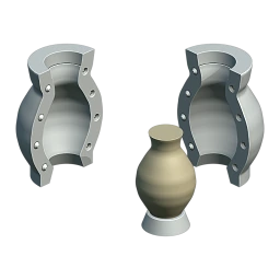
A plaster mold for ceramic slip casting. Cage Mold designs the plaster pieces and builds a printed system to pour them in: a model plate (the model's copy, the walls that part the pieces and the base plate) and a case round it. You print the model plate and the case, soap them and pour the plaster into the chambers between them in one go; once the plaster has set you take the pieces out, dry them and slip cast with them.
Vessels such as vases, cups and bottles are poured through their rim; figures through their base, the mold turned over. Cage Mold allows for the clay's firing shrinkage (Shrinkage), puts natches on the pieces' seams, shows in red the faces that would lock in the mold and tells you the plaster and water to mix for each piece.
Words
- Model
- The piece as it comes out of the kiln; your mesh. A vessel modelled with its walls (hollow) is used as the solid its outside bounds: the plaster meets only the outside, the cast makes the inside. A foot ring's recess is kept.
- Cavity
- The model grown by the Shrinkage; the slip fills it.
- Opening
- Where the slip goes in and out: a vessel's rim (Rim) or a figure's base (Base).
- Spare
- The extra above the opening: it holds the slip's level while casting and is cut off afterwards.
- Pieces
- The side pieces and the bottom piece. They lock to each other with natches.
- Natch
- A cone on a seam face and the hollow it fits on the other: the pieces close only the right way.
The seams in the scene
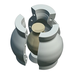
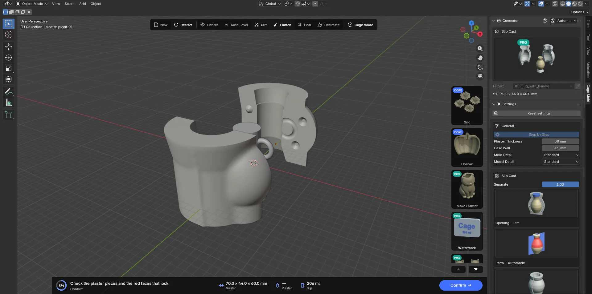
Once Slip Cast is chosen and a model is in, Cage Mold checks the model's undercuts ("Checking the undercuts…"; the check starts half a second after the last change and runs in a process of its own). When it is done the seam guides appear in the scene: an upright half-plane for each seam, out from the model's axis. The faces a piece would lock on are shown red on the model. The Slip Cast section writes Automatic's choice ("Automatic: 3 pieces at 30°") and the share that locks. Turn the guides about the upright axis with Blender's R: with Parts on Automatic, Parts switches to the count the guides show; the Turn field (shown only when Parts is not Automatic) follows the turn. Choose the number of pieces and the turn so that no red face is left.
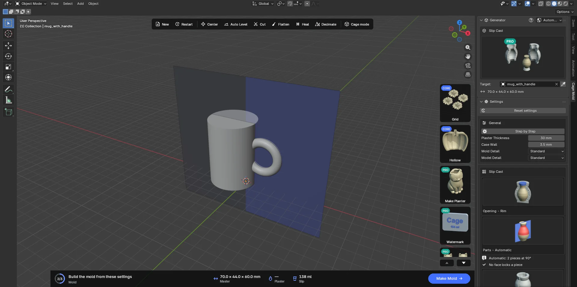
Settings
General: Plaster Thickness (30 mm; the plaster round the cavity, 25 to 50 mm in practice), Case Wall (3.5 mm; the printed case's wall), Mold Detail and Model Detail. The silicone settings, Undercut Fill, Split Planes, Channels, Top, the base keys and Casting Box do not apply to this type.
| Setting | Default | Meaning |
|---|---|---|
| Opening | Rim | Rim: a vessel, poured over its rim as the model stands. Base: a figure, poured through its base with the mold turned over (head down). Cards with pictures. Choosing Base switches Spare to Pour Holes, Rim back to Collar. |
| Parts | Automatic | The number of side pieces: Automatic, 1 to 6. Automatic picks the count and turn that lock least. 1 is a one-piece (drop-out) mold: the cast lifts out through the opening. |
| Turn (°) | 0 | Turns the seams about the upright axis (with Automatic the check's turn is used). |
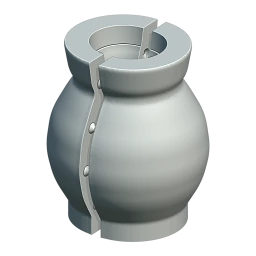
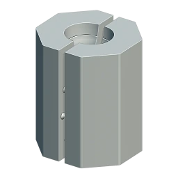
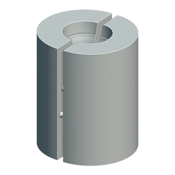
| Outside | Contoured | Contoured: follows the cavity at Plaster Thickness; even absorption, the least plaster. Prism (Faces, 8) or Round. |
| Shrinkage | 12 % | The clay's total shrinkage, wet to fired. The cavity is the model / (1 − Shrinkage). Enter your clay's data-sheet value. |
| Bottom Piece (its title bar is the switch; on) | ||
| Shape | Plain | The bottom piece's outline: Plain, round and smooth (easy to clean), or Model's Outline (the model's own, scalloped on a ribbed model). |
| Taper (°) | 20 | The bottom piece's sides, from the upright. |
| Ring Wall | 2 mm | The thinnest wall of the ring in the bottom piece's own mold. |
| Spare | ||
| Spare | Collar | Collar: a plaster collar; the clay in it is cut off at the rim. Printed Spout: a printed ring that sits on the mold and absorbs no water; the rim needs no trimming. Pour Holes (a figure): round holes through the plaster into its base. |
| Shape | Plain | The collar's or spout's outline: Plain or Model's Outline. |
| Height | 25 mm | The collar's or spout's height over the rim, the holes' over the base. |
| Cut Step | 2 mm | The collar starts this much wider than the rim: the knife's guide. |
| Flare (°) | 10 | The collar's and spout's walls lean out. |
| Contact Ø · Opening Ø · Holes | 25 · 35 mm · Auto | Pour Holes: a hole's width where it meets the model (the hole the cast keeps), at the plaster's top, and how many (Automatic: one for each separate part of the base, at most 4). |
| Natches | ||
| Count · Size · Height · Tolerance | Auto · 16 · 5 · 0.3 mm | Natches on each side of a seam (Automatic: 2 to 4 by height, or 1 to 6), the cone's base, its height and how much smaller the male natch is. |
| Pour | ||
| Split Wall | 3 mm | The printed wall between two side pieces. |
| Consistency | 70 | Water per 100 plaster by weight (USG No. 1 Pottery Plaster's normal consistency). Enter your plaster's value. |
| Printing | ||
| Model Plate | Single Plate | Single Plate: the plate, the master copy and the walls in one print. Part by Part: one print a side piece, pinned to the next; so a large mold fits the printer. |
| Print Height | 256 mm | Your printer's build height. A taller model plate or case part is cut in height into tiers that stack on pins; the case tiers are held by clips. |
| Clamps | ||
| Case Ears · Pour Clips | 6 × 7 · 10 / 4 mm | The case's ears (Width, Depth) and the clips that hold them over the split wall while pouring (Height, Thickness, Tolerance, Clip Grip). |
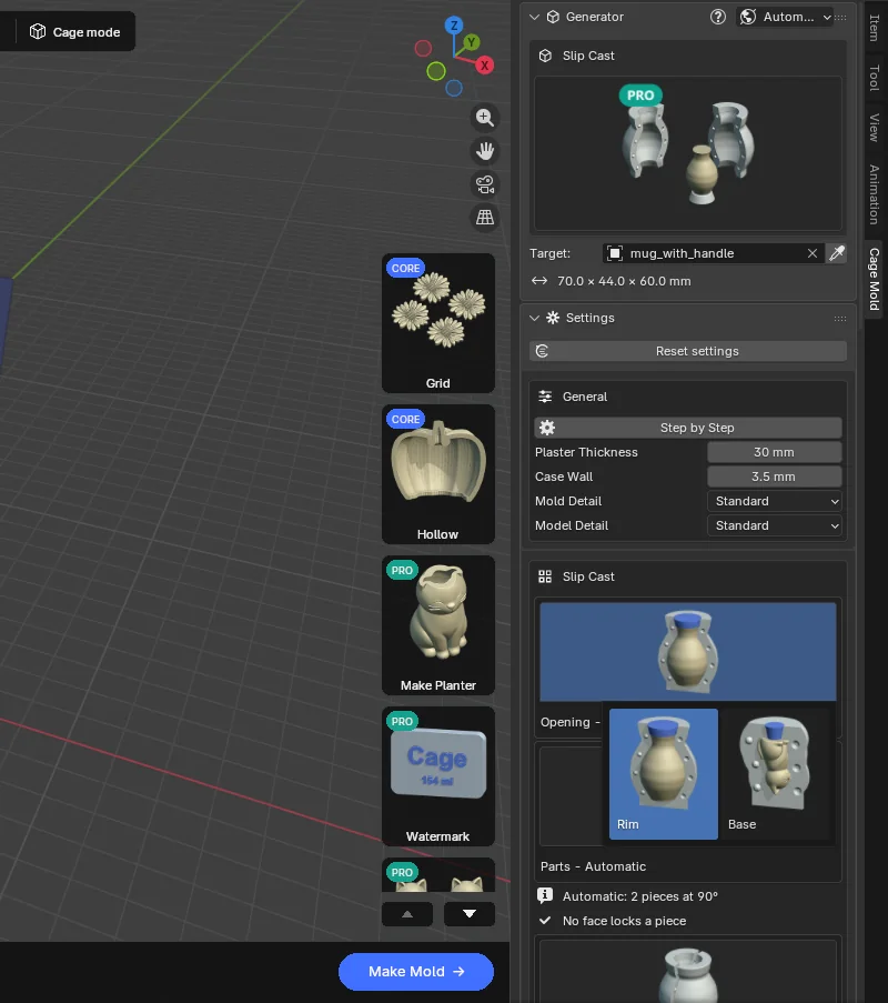
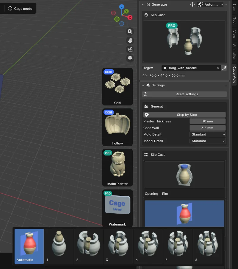
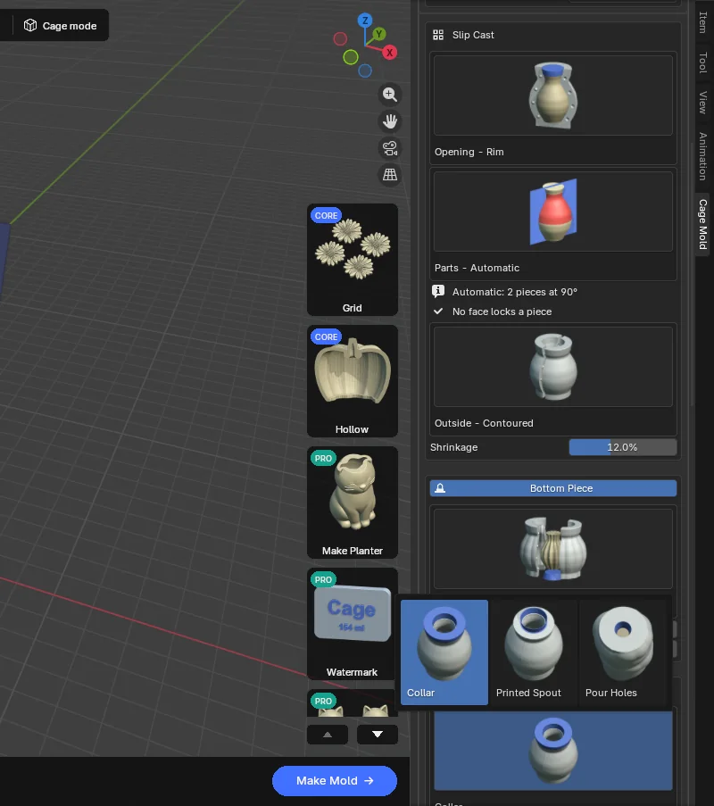
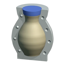 Rimdefault
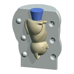 Base
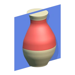 Parts · Automatic
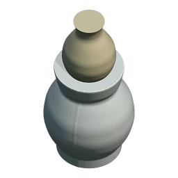 Parts · 1
 Parts · 3
 Contoured
 Prism
 Round
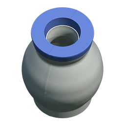 Collar
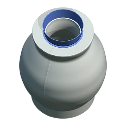 Printed Spout
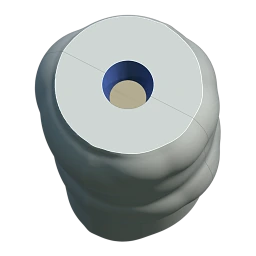 Pour Holes
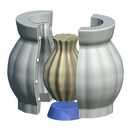 Bottom Piece · Plain
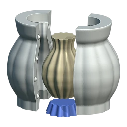 Bottom Piece · Model's Outline
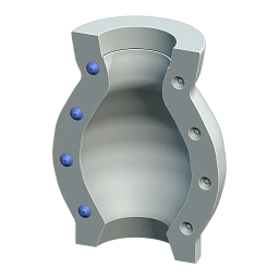 Natches
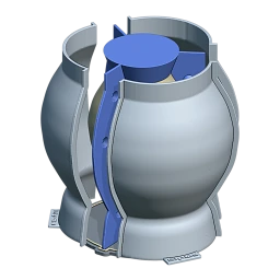 Pour
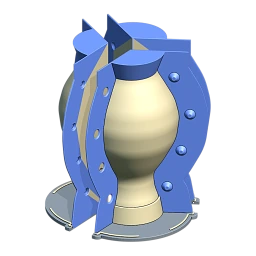 Model Plate · Part by Part
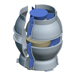 Print Height · tiers
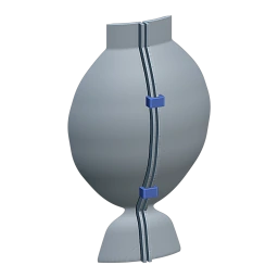 Clamps
Workflow
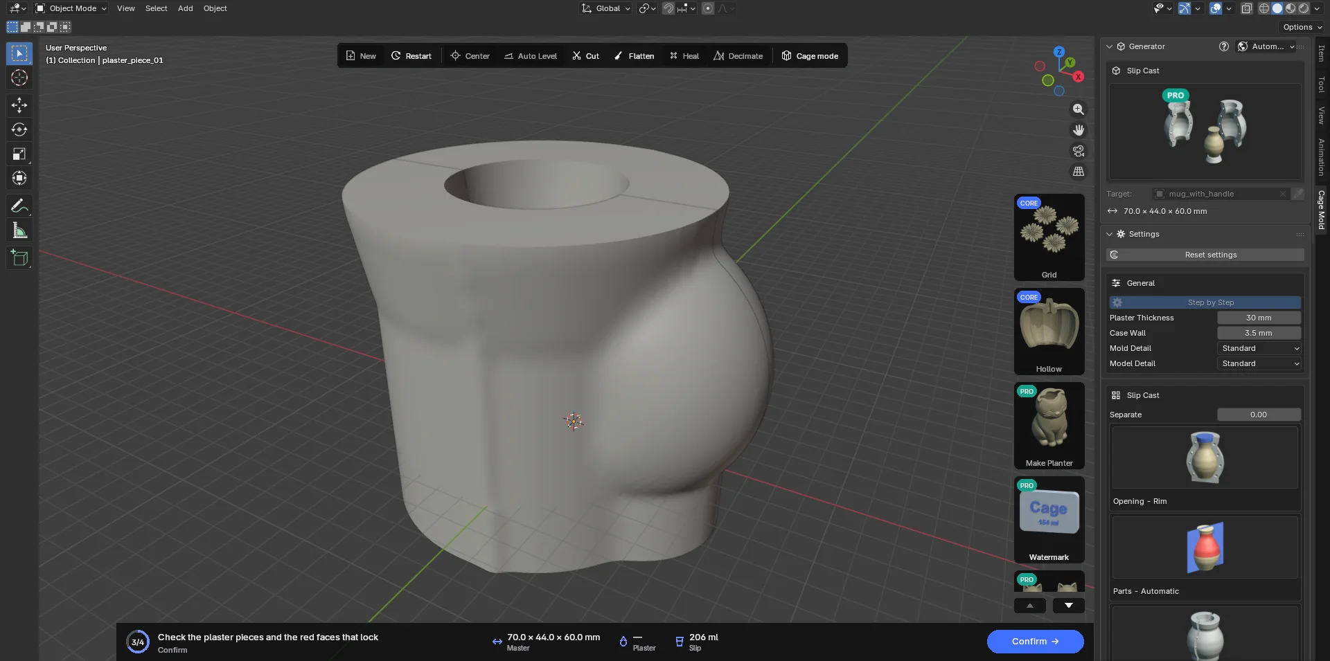
As for the other types: Make Mold in Automatic; in Step by Step first Make Draft, then Confirm. Make Draft lays out the plaster pieces: they stand drawn out from the model along their pulls, the locking faces red. The Separate slider (0 to 1) closes and opens them without a rebuild. Confirm builds the printed system at full detail. The action card's figures become Plaster (the plaster and water to mix, "3.67 kg + 2.57 L") and Slip (the slip that fills the mold, "2.07 L").
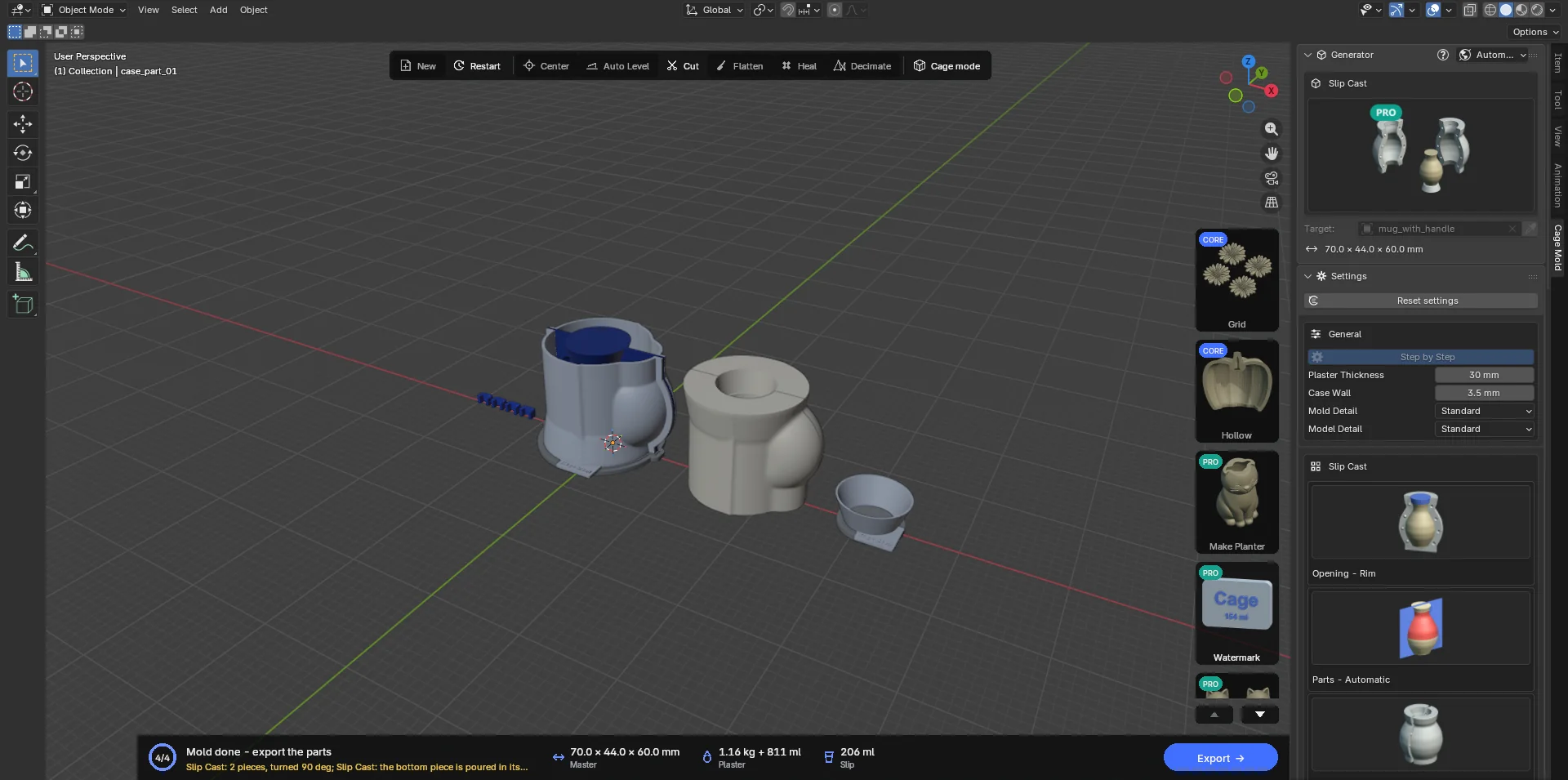
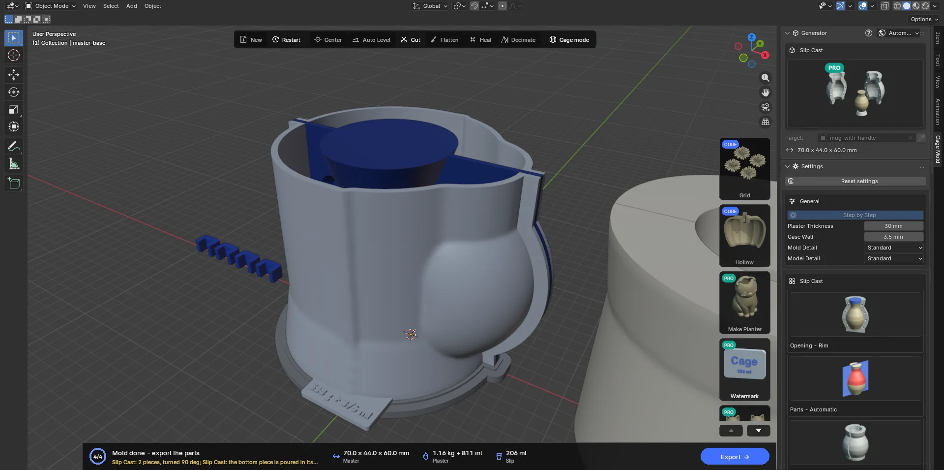
The parts and the casting sheet
- Printed:
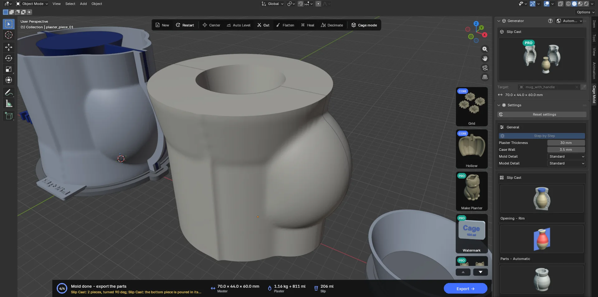
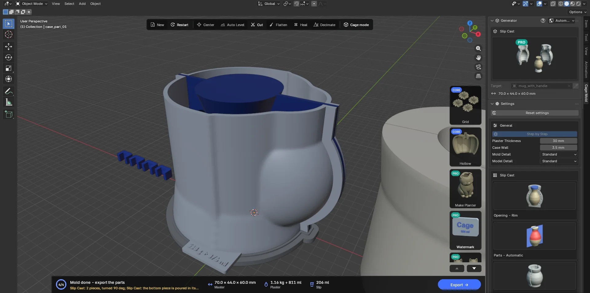
master_base(the model plate; with Part by Partmaster_base_part_01…, in tiers…_tier_1…), the case partscase_part_01…, the pour clips, the tier clips, the bottom piece's mold (bottom_piece_ring,bottom_piece_floor) and, with Printed Spout, thespout. Every case part carries its own piece's plaster and water on its foot ("1240 g + 868 ml"). - Not printed: the plaster pieces' preview (
plaster_piece_01…,bottom_piece); Export writes them and the cavity's model into areferencefolder. - The casting sheet: Export also writes
<model>_casting_sheet.pdf: a page in Cage Mold's language that prints on A4. The mold's settings, the plaster and water piece by piece, the slip, and the order of work with its times: print, assemble, soap (two or three thin coats), weigh and mix (water at 21–38 °C, soak 1–2 min, mix 1–2 min), pour at once, demold after 45–60 min, wash, dry at no more than 49 °C until the weight stops falling; then strap the pieces, pour and top up the slip, drain, cut the rim, open the mold. - Confirm measures every printed part against a 256 × 256 mm bed and the Print Height and names those that do not fit, with their size; when the single model plate does not fit but Part by Part's pieces would, it says so.

7.7 Injection Mold PRO
Two rigid halves and one cavity for a desktop plastic injection machine. The nozzle presses onto the sprue at the mold's top edge. Molten plastic passes through the sprue and gate into the model's cavity; shallow vents let the air out. After the plastic cools, the mold opens and the part comes out.
Your model is the cold part's shape. Shrinkage enlarges the cavity for the plastic's contraction; Density changes the shot's weight calculation. The action card's Shot includes the cavity, sprue and gate. Enter the machine's capacity in Max Shot, in cm³ (0 turns that check off).
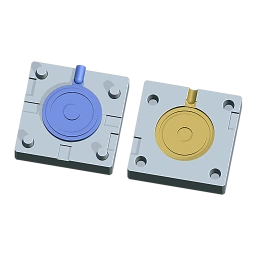
Vise or Frame Insert
Vise: the block grows around the cavity and behind each half by Mold Wall (10 mm by default). Its outside size follows the model and the space needed by the feed. Hold it in a vise under the vertical nozzle. The default Printed Pins puts tapered pins on B and matching sockets in A.
Frame Insert: each half is a fixed block for a metal frame's pocket. The built-in size is 76.2 × 86.6 × 25.9 mm: Width across, Height along the sprue, Thickness for one half along the pull. Clearance defaults to 0.2 mm on each side of Width and Height (a 75.8 × 86.2 × 25.9 mm block with those settings); Thickness is kept. Measure your actual pocket and check which edge faces the machine top; the preset does not guarantee a fit. The +/− buttons save or remove your own size. Alignment defaults to None because the frame aligns the halves. A model or feed that cannot fit produces a size error.
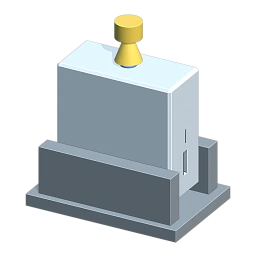
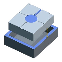
Locks and draft
Pull is the axis along which the halves leave the part: A opens in the positive direction, B in the negative. Automatic chooses the axis and parting height that lock least among X/Y/Z. Turn rotates the machine top around the pull by 0/90/180/270°; the original model stays in place. The Parting plane is flat; set its Height or move its guide along the pull with G.
A red face is a lock: its half would catch, drag or break the part while opening. A yellow face is below the chosen Draft Angle and may drag. Draft is the face's angle to the pull (the default check threshold is 1°). Cage Mold checks and shows it; it never adds draft or repairs locks on the model. The threshold is not a guarantee of enough draft for your material.
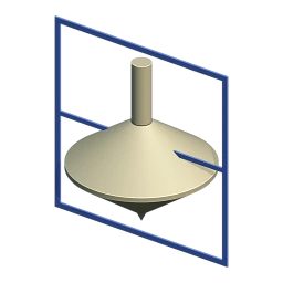
Feed and Automatic rows
Sprue Ø defaults to 4.8 mm. Sprue Top is Straight or Cone: Cone opens a funnel Top Ø across at the top edge (8 mm by default) that narrows to Sprue Ø, a seat for a bigger or smaller nozzle. With Gate set to Automatic, the gate is chosen on the outside outline: of the places where the part is as thick as anywhere (80% of its thickest wall is enough), the one nearest the nozzle, so the sprue stays short. Pick Gate uses the outside outline point nearest your click on the model. Gate Thickness, Gate Width and Vent Count each have an Automatic switch. Turn it off to enter a number; toggling it on and off restores your manual number. Values in existing saved files are kept.
Automatic gate thickness is 60% of the wall at the gate (0.8–3 mm, capped by the wall thickness); width is 1.5 times that thickness (from 2 mm up to the sprue's diameter; never wider than the sprue). Gate Land defaults to 1 mm. Automatic vents target one per 40 mm of outline, 2–6 in total; the manual count is 1–8. If fewer fit, a note says so. Vent Width / Vent Land default to 6 / 2 mm. Mold Material sets vent depth: Carbon FDM 0.10 mm, Resin 0.05 mm, Aluminium the selected plastic's value. These numbers remain editable; changing plastic or mold material reapplies its dependent defaults.
Print the halves and make the first shot
- Choose the part and machine
Import the model in mm; choose Injection Mold and Vise or Frame Insert. Enter the frame pocket size and machine shot capacity. Choose the plastic, shrinkage and mold material, checking them against your actual material's data.
- Check how it opens
Use Step by Step. Inspect the parting guide, red locks and yellow faces. Adjust Pull, Turn and Parting; edit your source model if needed. Check the gate and vent positions.
- Draft, confirm and export
Make Draft shows the halves drawn apart. Confirm builds full detail and lays them out backs down, parting faces up. Check shot volume/weight and capacity, lock and thick-section notes. Export's printable pieces are
injection_half_bandinjection_half_a; the shot and cavity meshes inreferenceare for inspection. - Prepare heat-resistant halves
Use a carbon-fibre filament (PET-CF, PA-CF or PPS-CF) or heat-resistant rigid resin. PLA, PETG and ABS soften under the nozzle. Slice with the parting faces up; the 0.10 mm FDM vents are shallow, so verify that they remain open in the slicer. Follow the material's printing, drying and resin post-curing instructions. Clear residue from the cavity, sprue, gate and vents; check that the faces close and the pins seat.
- Close and make the first shot
Close the halves and hold them in the vise or the metal frame whose fit you checked. Align the sprue entry under the nozzle. Follow the machine and plastic manufacturers' temperature, clamping, pressure and cooling instructions; Cage Mold does not calculate these process settings. Try the first shot and let it cool.
- Open, inspect and adjust
Follow the machine's pressure-release and removal sequence, then separate the halves along their pull. Use the Pry Slots where present. Remove the part and separate the sprue at the gate. Inspect incomplete filling, flash, trapped-air marks, sink and drag. Adjust the feed, vents or source model as needed and check again; complete filling and mold lifetime are not guaranteed.
Limits
This phase covers desktop machines, two halves, one cavity and a flat parting plane. There is no flow simulation: gates and vents follow rules and do not promise a full shot. The model is never changed and draft is never added. STEP output, steel production tooling, moving cores, ejector systems and multiple cavities are outside this phase. First-shot validation on a real machine is a separate step; a mesh check is not a heat or pressure test.