Interface tour
With Cage Mold's tab open there are five pieces on screen: the sidebar, the tool strip, the tool cards, the action card and the split guides in the view. All of them are drawn over Blender's own view and change none of its settings.
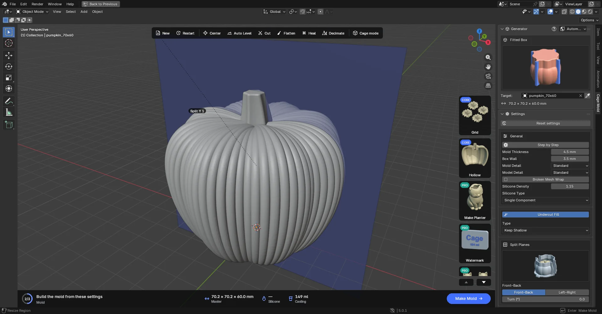
The sidebar
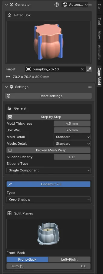
N, with the mouse over the 3D view, opens and closes the sidebar; choose Cage Mold among the vertical tabs at its right edge. From top to bottom the tab holds:
- The Account and update rows (only when needed): the sign-in box when you are not signed in (chapter 2), and "Version X is ready" with Update when a newer version is out (chapter 2).
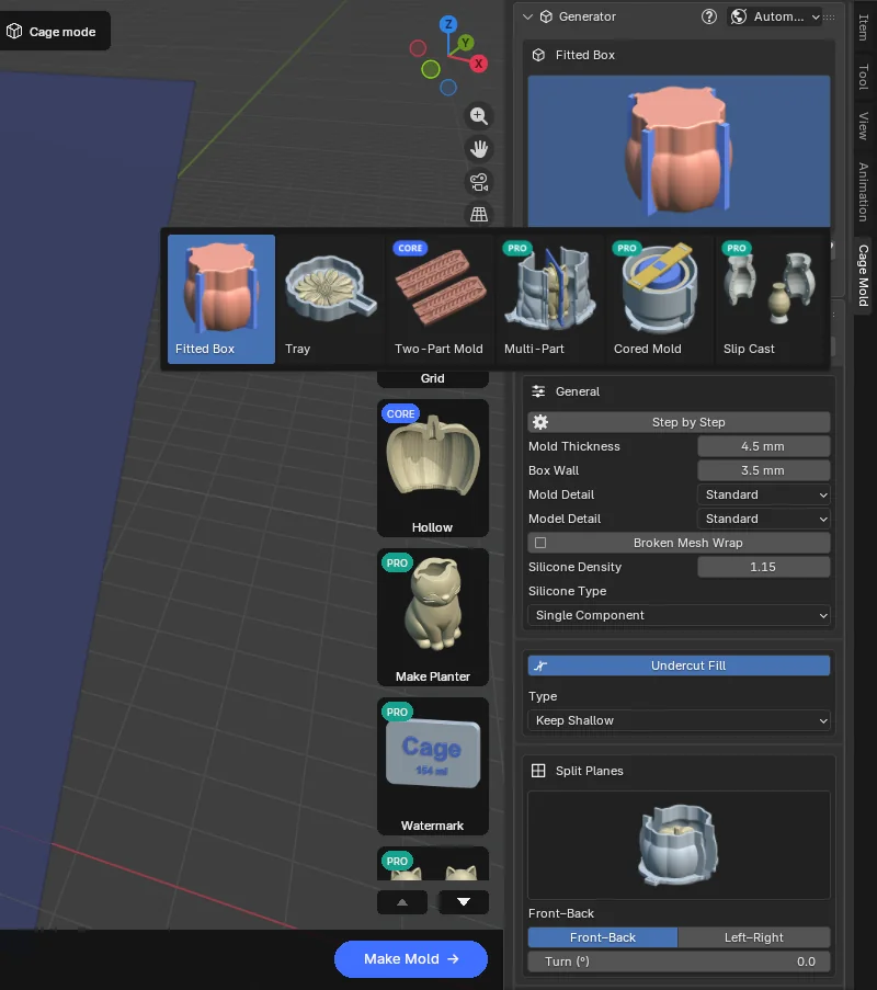
- The Generator panel: the mold type's name and large picture. The picture is also its chooser: a click opens the seven types as small cards, a click on one chooses it. Holding the mouse over a card shows its description. A type your package does not hold brings a lock box under the picture.
- Two buttons at the right of the Generator header: ? opens the Help menu (red, with a number, when a support answer is new) and the globe picks Cage Mold's language (chapter 2).
- Target: the model the mold is made for. Pick another object from the list, or make the object selected in the view the master with the eyedropper beside it. Under it the model's size is written (X × Y × Z, mm). The model is chosen before the mold: after Make Draft the field is greyed; use Restart or New for another model. A model under 5 mm or over 1 m was probably saved in another unit; a box says so and offers scale buttons: × 1000 (from metres), × 25.4 (from inches) and × 10 (from centimetres) for a small model, × 0.1 and × 0.001 for a large one.
- The Settings panel: the settings in sections (General, Undercut Fill, Split Planes, Channels, Base, Top, Clamps, Silicone, Casting Box and one for the chosen type). Sections the type does not use are hidden. Reset settings at the top restores every setting to its default.
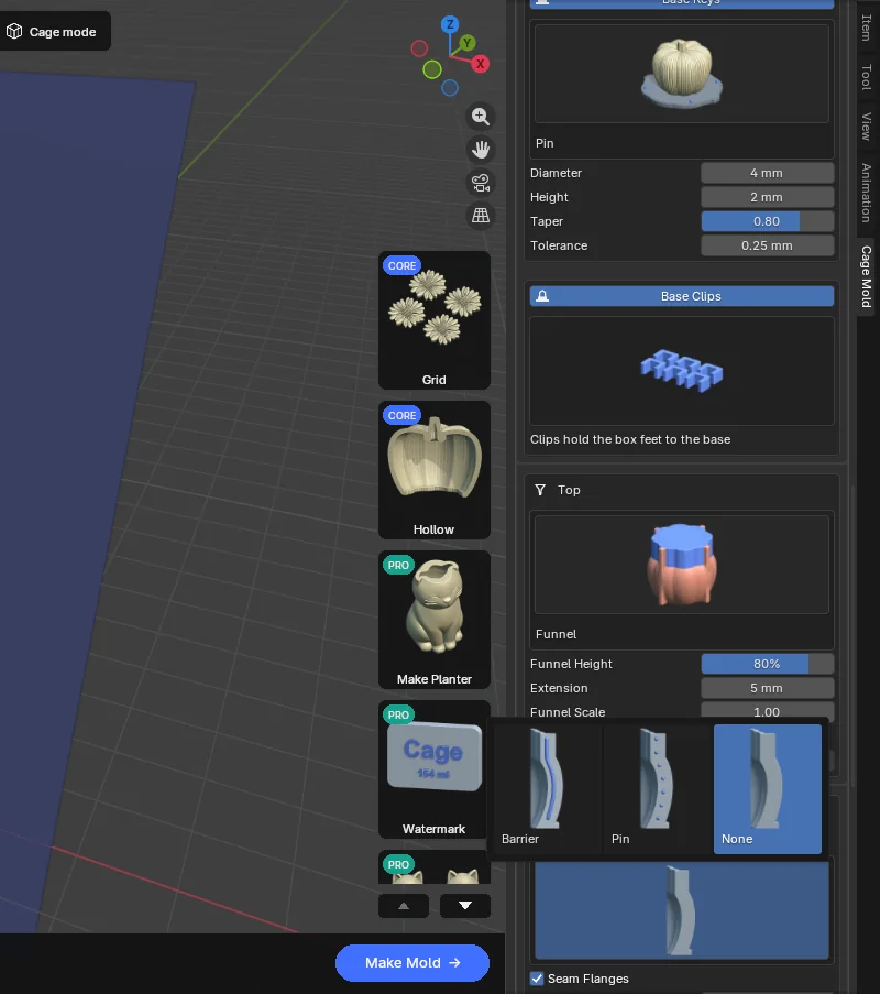
Sections are boxes with no arrows; they never collapse. For sections one switch turns on (Undercut Fill, Channels, Model Pins, Base Keys, Base Clips, Casting Box, Grip, Open Bottom, Wick Channel, Bottom Piece) the title bar is the switch: a click colours it and turns the section on, another leaves it plain; while off, its content stays visible but greyed. Every setting has a row of its own: its name on the left, its value with its unit on the right. Holding the mouse over a setting says what it does.
The tool strip

The strip carries the tools that prepare the model. Holding the mouse over a button shows its description. When room is short the buttons go into two rows, and into icons alone when even that does not fit. Blender's own Move, Rotate, Scale and Measure tools are already in the toolbar on the left, so the strip leaves them out (Cage mode adds them to its top bar).
- New: imports an STL, OBJ or 3MF file; the model is centred and stood on the floor.
- Restart: removes everything generated and keeps the model; you start over. Ctrl+Z undoes.
- Center, Auto Level: centre the model, lay its largest flat face on the floor.
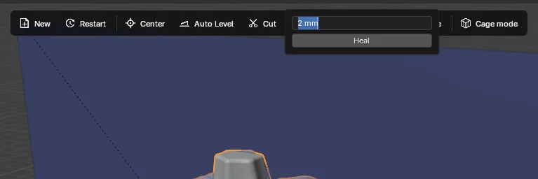
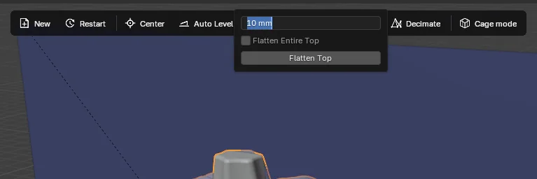
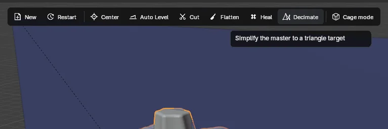
- Cut, Flatten, Heal, Decimate: open a small popover; enter the values and press the button. Details in chapter 5.
- Cage mode: switches to Cage mode, which hides Blender's menus.
A greyed button cannot run now: for example Center does not work while a mold exists; Restart first.
The tool cards
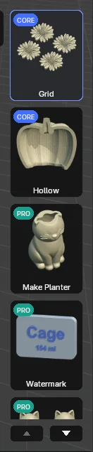
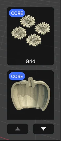
Five cards stand in the column at the right edge of the view: Grid, Hollow, Make Planter, Watermark and Pocket Fill. A click on a card opens the tool's dialog; holding the mouse over it shows its description. Cards that cannot run now stay dark (with no model, or while a mold is being generated). The CORE or PRO badge in the top left corner says which package holds the tool.
When a tool has a result that can be taken back, a small × appears in the card's top right corner: it removes the grid, undoes Hollow and Make Planter, deletes the watermarks, drops the Pocket Fill pieces. The cards are always full size; when the column does not fit the screen, an up/down arrow bar appears under it: an arrow moves the column one card, and the mouse wheel over the column does the same.
What the cards do is in chapter 6.
The action card

The action card is a slim rail along the bottom edge of the view: it shows where you are and what comes next. Blender's Adjust Last Operation panel keeps the bottom-left corner; the rail starts right of it.
- The step ring (left): the step you are at, such as 2/3. The steps are Master, Mold, Export; in Step by Step Master, Draft, Confirm, Export; on a tray Tray stands for Mold or Draft. The ring fills cobalt as far as you have come and spins while a job runs.
- The hint (beside the ring): one line on the next step, with the step's name under it. While a job runs it gives the stage ("Filling undercuts") over the seconds and Esc to cancel. A note from Confirm (a pin made smaller, a hollow left without a core) stands under the hint in yellow.
- The figures (middle): each an icon, its value and its word under it. Master: the model's size (or, with an object selected, its size and name). Silicone: the grams of silicone to pour; with A/B silicone each part's share, the whole beside the word. The grams come once the mold is built; until then it reads "—". Casting: the volume of material the mold takes, known as soon as a model is chosen. On the Lite package the last two read CORE in the package's colour. On Slip Cast the figures are Plaster (plaster and water) and Slip (the clay). On Injection Mold one figure, Shot, takes their place: the volume and weight of the cavity, sprue and gate.
- The primary button (right, pill-shaped): does the next step. Its name follows the stage: Import → with no model, then Make Mold → (Make Draft → in Step by Step, Make Tray → on a tray), Confirm → and finally Export →. With the mouse over the view, Enter presses the same button; the right end of the status bar says which. While a job runs, Esc cancels.
When the view gets narrow, the words on the left shorten first, then a selected object's name is cut, then the last figures are left out; a very narrow view shows no rail. When a build fails, the error stands on the left in red and a Report this error button comes beside the primary one (chapter 10). While Pocket Fill pieces wait, the right end carries three buttons (6.5).


The guides in the view
Once a model is chosen a blue square appears in the view: the split guide ("Split Y 1"). The box splits in two along this plane. Move the guide with Blender's own tools: click it, press G, move the mouse and click to drop it. The Turn (°) field in the Split Planes section turns the guides together. The guide disappears with Make Draft or Make Mold, so the split is set before the build. A build cancelled with Esc, or one that fails, puts the guides back where you left them, turned as they were.
Two-Part Mold shows a fixed parting plane instead of a guide; a Tray has none; Slip Cast shows its pieces' seams as upright half-planes (7.6). Injection Mold shows a flat parting guide that G moves only along the pull; the model's locking faces turn red and those under Draft Angle yellow (7.7).
The guides and their labels hide together with Blender's Show Overlays / Show Gizmos switches; the strip, the cards and the action card do not.
The view follows the model. A model that arrives (dropped, through Blender's Import or with New) is centred and framed in every view that shows Cage Mold's tab. Once the scene is in millimetres the floor grid steps 10 mm. A cube or sphere from Blender's Add menu is not taken for the model. Delete the model and Target empties.
Icons
The panel headers and the strip use Cage Mold's own icons, light on a dark theme and dark on a light one.
 Generator
 Settings
 General
 Undercut Fill
 Split Planes
 Channels
 Base
 Top
 Clamps
 Silicone
 Casting Box
 Tray
 Cored Mold
 Two-Part
 Multi-Part · Slip Cast
 New
 Restart
 Center
 Auto Level
 Cut
 Flatten
 Heal
 Decimate
 Move
 Rotate
 Scale
 Measure
 Cage mode
 Reset settings
 Refresh Preview
 Recenter Planes