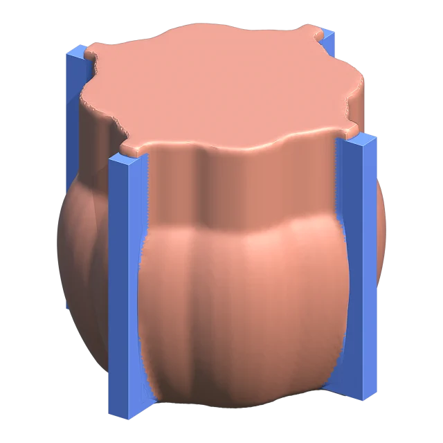
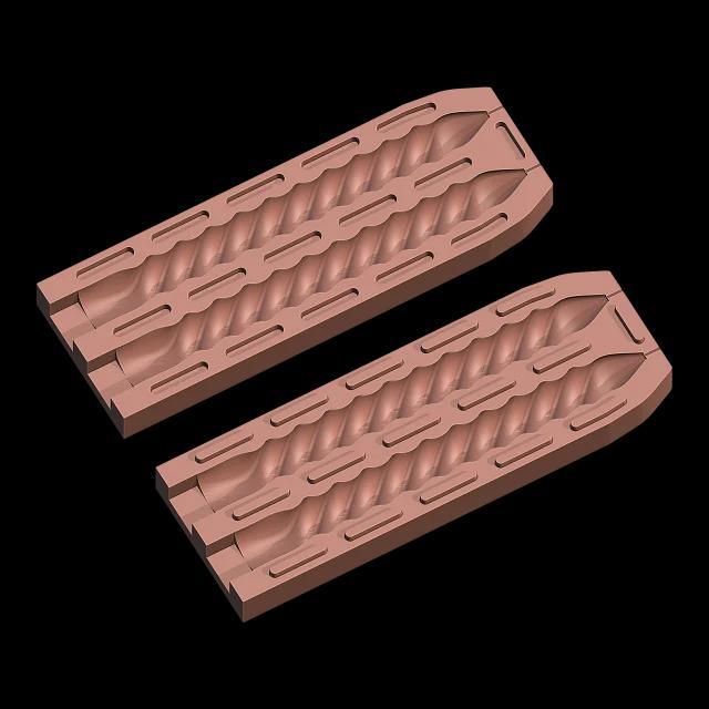
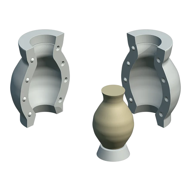
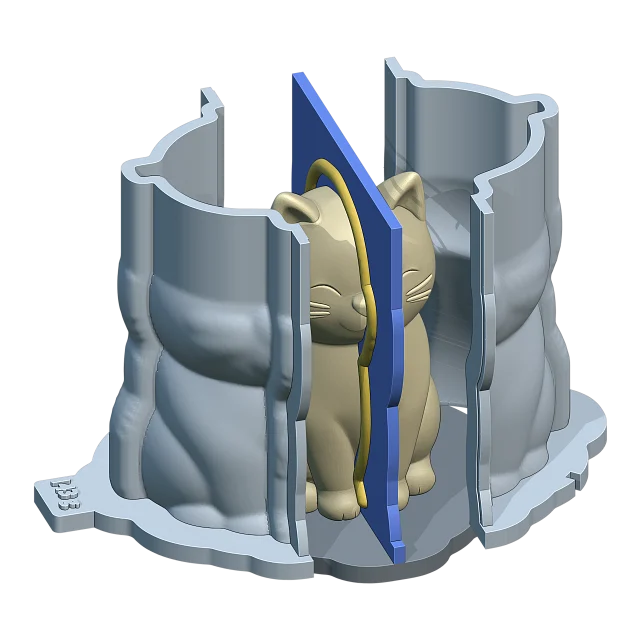
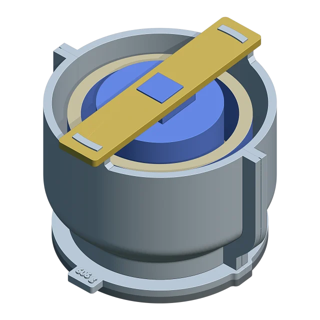
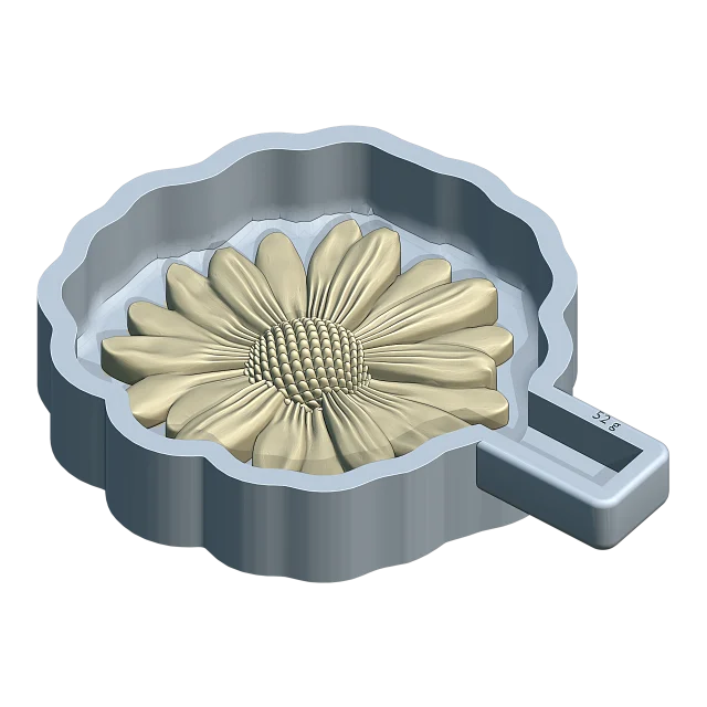
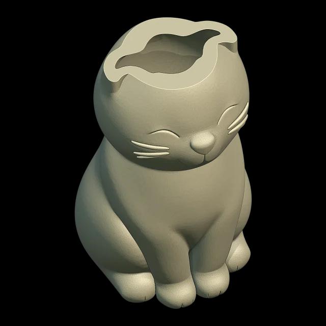
How the mold works
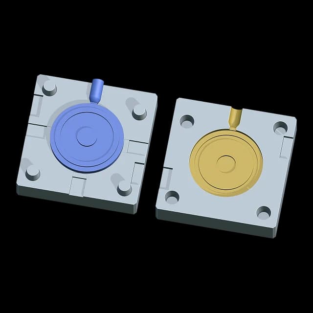
The mold is two rigid halves that meet on the parting plane, with the cavity, the part's shape, between them. The machine's nozzle presses on the mold's top edge; the plastic runs down the sprue and through the narrow gate into the cavity, and the air it pushes out leaves through shallow vents. Once the plastic has cooled, the halves are pulled apart and the part comes out.
- Cavity: the part's shape, grown by the plastic's shrinkage.
- Sprue: the round channel from the nozzle to the gate.
- Gate: the narrow mouth into the cavity, where the part is broken off.
- Vents: slots shallow enough to let the air out but not the plastic.
What you need
- A desktop injection machine with a vertical nozzle, and a vise or the machine's metal frame.
- The part as a closed solid in millimetres, at its finished size.
- A heat-resistant mold material: a carbon-fibre filament (PET-CF, PA-CF, PPS-CF) or a heat-resistant rigid resin. PLA, PETG and ABS soften under the nozzle.
- The plastic's data sheet, for its shrinkage and the temperatures its maker gives.
- Calipers, to measure the frame's pocket and the first parts.
1. Check the part: the pull and the draft
The two halves leave the part along one axis, the pull. A face that hooks behind the part along its half's pull locks the mold: a hole across the pull, a lip, an overhang. Two halves cannot release it; change the design, or turn the part so it pulls another way.
Walls parallel to the pull drag as the mold opens. A slight slope, the draft, lets the part slide free; a printed mold needs more of it than polished steel, and the part's design should carry it.
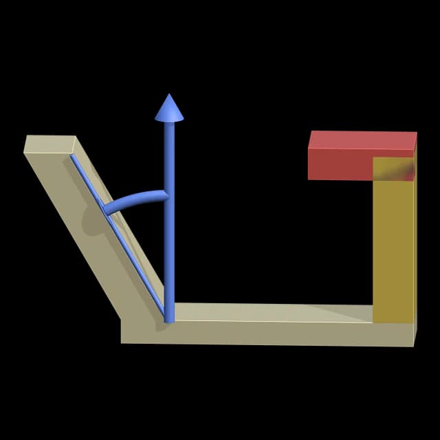
In Cage Mold: Pull Automatic takes the axis that locks least, and before you build, the faces that lock show in red and those under the Draft Angle (1°) in yellow. Cage Mold checks the draft; it never changes your model.
2. Place the parting plane and grow the cavity
The parting plane is where the halves meet, and it leaves a fine line on the part. A part with a flat back is the easiest: the plane lies at its back, the whole cavity is in one half and the other half is flat.
Plastic shrinks as it cools, so the cavity must be larger than the part: cavity = part / (1 - shrinkage). PP shrinks about 1.8 %, ABS about 0.5 %; your plastic's data sheet has its figure.
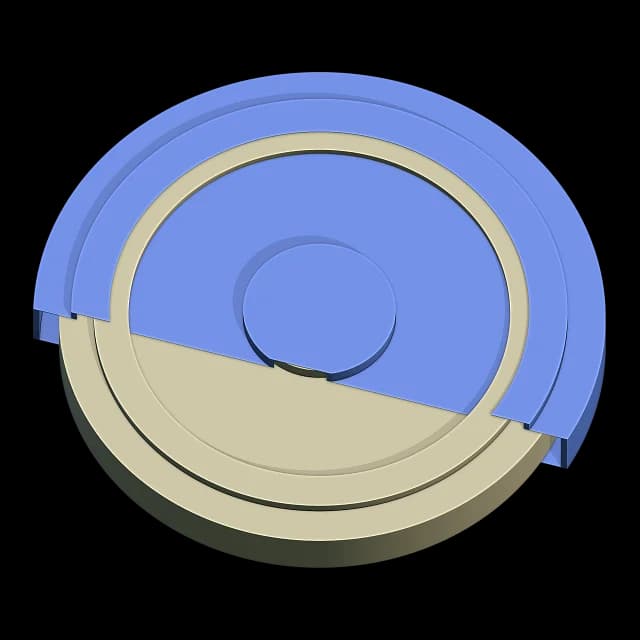
In Cage Mold: Parting Automatic takes the height that locks least, and a flat back when the part has one; Height or the guide sets it by hand. Plastic is PP, HDPE, LDPE, ABS, PS, PC, PA6, POM, TPE or Custom, and sets Shrinkage (1.8 % for PP) and Density.
3. The sprue and the gate
The sprue starts as a round hole in the top edge, where the nozzle seats, and runs down in the parting plane, half in each half, so it opens with the mold. Desktop nozzles are about 3-5 mm across, and the sprue is about as wide; a cone at the entry seats a larger or smaller nozzle.
The gate is the narrow neck between the sprue and the cavity. Put it where the part is thickest, so the plastic flows from thick to thin, and as near the nozzle as that allows, so the sprue stays short and wastes little plastic. A thin gate breaks off cleanly.
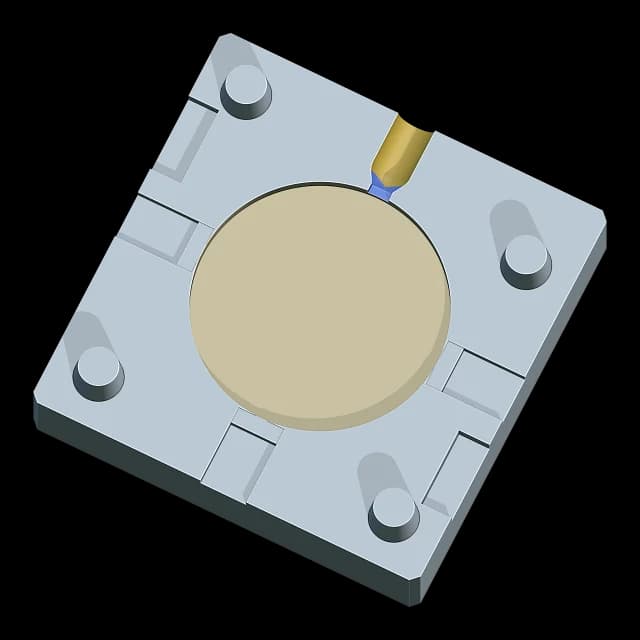
In Cage Mold: Sprue Ø is 4.8 mm, Sprue Top Straight or Cone (Top Ø 8 mm). Gate Automatic puts the gate where the part is thickest and nearest the nozzle; Pick Gate puts it where you click. Its thickness is 60 % of the wall there, 0.8-3 mm, and it is never wider than the sprue.
4. Vents, pins and the shot
Air trapped in the cavity stops the plastic short or burns the part. Vents are slots in the parting face from the cavity to the mold's edge, at the places the plastic reaches last, far from the gate. They must be shallow enough for the plastic to freeze in them: a few hundredths of a millimetre in aluminium, about one layer in a printed mold.
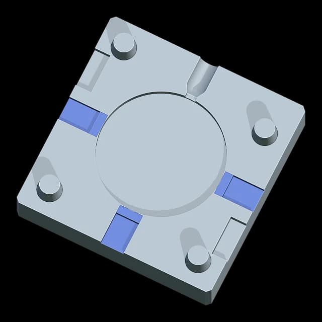
Pins keep the halves from shifting as they close, and slots at the seam let a screwdriver open them. Last, check the shot: the cavity, the sprue and the gate together must not be more than the machine pushes in one stroke.
In Cage Mold: Vent Count on Automatic makes one vent per 40 mm of outline (2-6), 0.10 mm deep in Carbon FDM and 0.05 mm in Resin. Alignment is Printed Pins, or Pin Holes for steel dowels; Pry Slots open the halves. The action card shows the Shot in cm³ and grams, and with Max Shot set, a note says when it is more.
5. A vise or a frame
In a vise the mold is a block that grows round the cavity, and the jaws press the halves together under the nozzle. Some desktop machines take a metal frame instead: each half is a block of a fixed size that drops into the frame's pocket, and the frame keeps them in line.
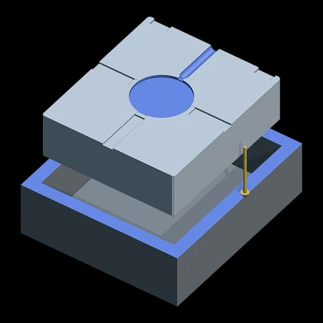
In Cage Mold: Machine is Vise (Mold Wall 10 mm round the cavity) or Frame Insert, 76.2 × 86.6 × 25.9 mm by default with 0.2 mm of Clearance. Measure your own pocket and type it in: the preset does not promise a fit. A part and its feed that do not fit the frame stop with their sizes.
6. Print and shoot
- Print the halves parting face up, in the material you chose, and check in the slicer that the shallow vents stay open.
- Follow the material's drying, printing or post-curing instructions, then clean the cavity, the sprue, the gate and the vents.
- Close the halves, check that the faces meet and the pins seat, and clamp them in the vise or the frame with the sprue under the nozzle.
- Set the temperature, pressure and cooling from the machine's and the plastic's makers, and shoot.
- Let it cool, open the halves along the pull and break the part off at the gate.
In Cage Mold: Export writes the two halves to print. Cage Mold does not set the machine and has no flow simulation: the gate and the vents follow rules, so shoot a first part, look at it and adjust.
Common mistakes
- A mold printed in PLA or PETG: it softens under the hot nozzle.
- Deep walls with no draft: the part sticks and drags.
- Vents too deep leave flash; vents too shallow, or closed by the slicer, leave short shots and burn marks where the air was trapped.
- Thick sections: over about 6 mm the plastic sinks as it cools.
- A shot larger than the machine's.
- A frame size from memory instead of the measured pocket.
In Cage Mold: Confirm's note warns when the part locks, when a section is thick enough to sink, and when the shot is more than Max Shot.
Try it in Cage Mold
Injection Mold is in Cage Mold's Pro package. The 7-day Pro trial opens every Pro tool on one computer, with no card: design the halves for your own part and check its locks, the gate and the shot before you print.
How much silicone do you need?
Type in the model's size; the calculator gives the silicone's volume, weight and the A/B amounts.